Mechanically buffered contact wiper

Inactive Publication Date: 2005-06-02
COCHRAN GARY D
View PDF5 Cites 1 Cited by
  • Summary
  • Abstract
  • Description
  • Claims
  • Application Information

AI Technical Summary

Benefits of technology

[0019] The buffer may be bonded to the surface on which a track is mounted, thereby sealing and isolating the resistive track in a 3-dimensional structure. The buffer material is selected to be resistant to chemical effects in the region of the wiper, and with low permeability for transfer of chemica

Problems solved by technology

However, soft copper doesn't exhibit good wear characteristics against mechanical contac

Method used


Image

  • Mechanically buffered contact wiper
  • Mechanically buffered contact wiper
  • Mechanically buffered contact wiper

Examples


Example

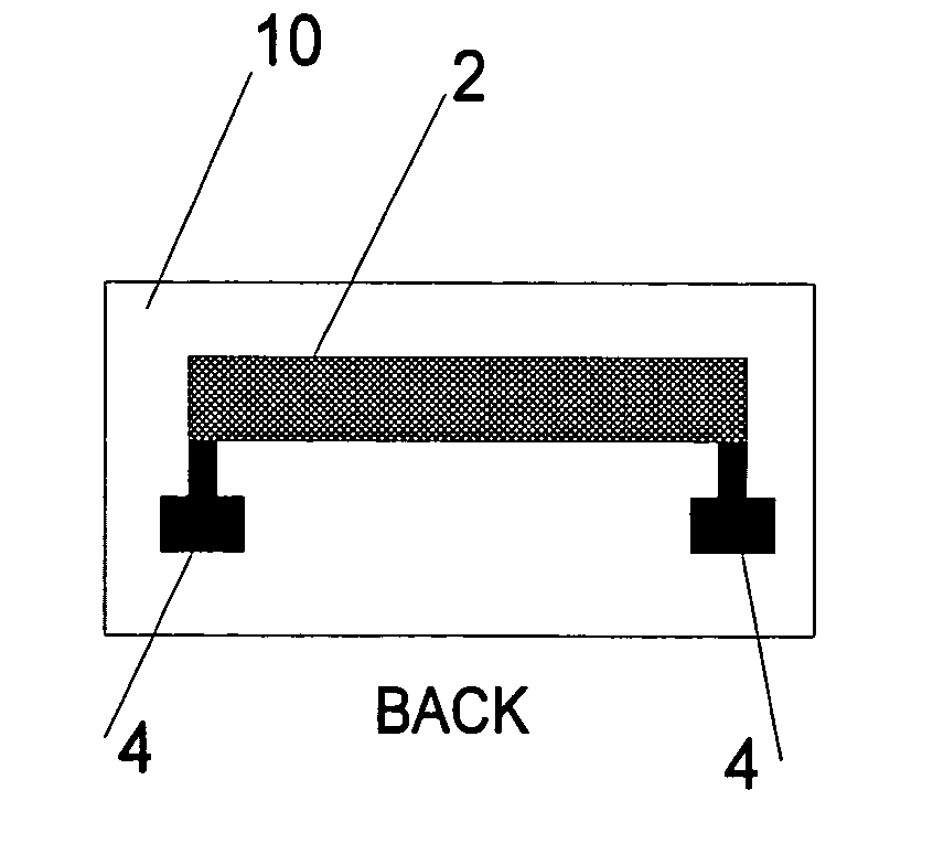
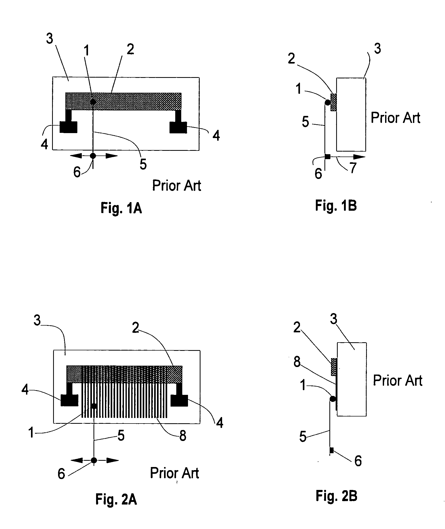
[0044]FIGS. 1A, 1B show a known potentiometer design whereby a wiper 1 slides directly on a resistive track 2 mounted or printed on a substrate 3. An arm 5 is mechanically moved to move the wiper. Although the track is shown as mounted along a line, it may be in almost any pattern, such as an arc when a wiper is pivoted about an axis. Conductive termination pads 4 connect the potentiometer to wires that are used to connect to external circuits (not shown) In some circuit uses only one pad 4 will be connected to an external circuit. Often a center tap 6 is used to split the potentiometer into two resistors each between the center tap and a respective one of the pads, with a wire 7 shown as an output lead. For a simple trimmer application the lifetime is adequate. For millions of repetitive cycles or closed loop servo operations the lifetime may be much too short.

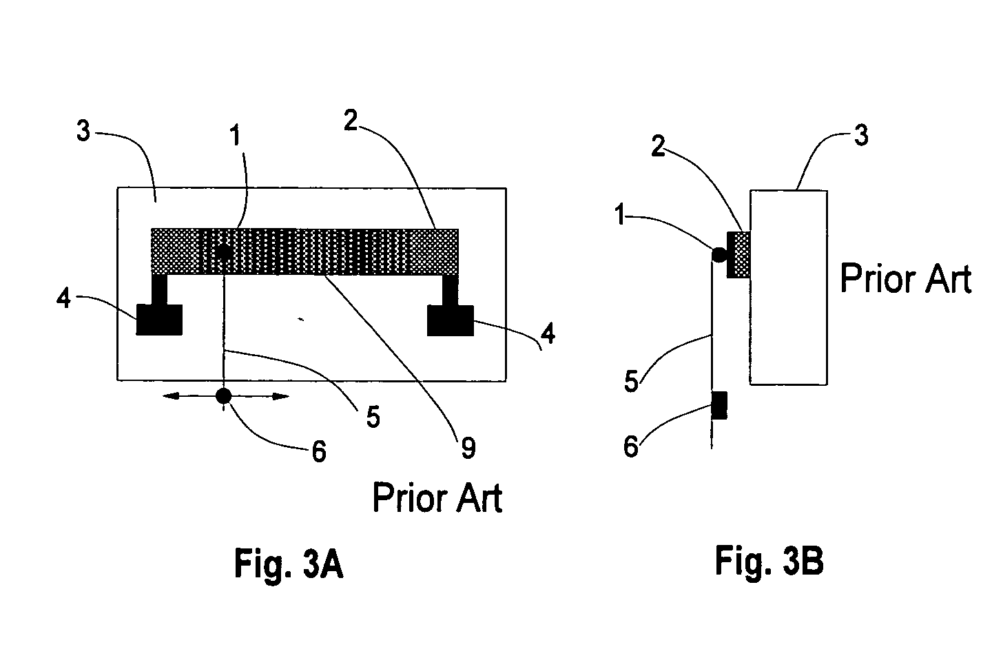
[0045]FIGS. 2A, 2B show a prior art potentiometer design used extensively in a fuel level sender. The commutator bars 8 ov...


PUM


Abstract

An electric device contains a medium interposed between first and second electric elements to provide electric continuity between the first element and a defined reference point of the second element throughout a defined range of sliding travel of one of the elements along the medium in a direction that is transverse to a favored direction of conduction through an electrically anisotropic conductive region of the medium that is composed of electric conductors that conduct in a favored direction and are electrically separated by solid dielectric.

Description

CROSS-REFERENCE TO RELATED APPLICATION AND PRIORITY CLAIM [0001] This non-provisional application derives from the following commonly owned co-pending patent application, the priority of which is expressly claimed: Provisional Application No. 60 / 525,737 filed on 1 Dec. 2003 in the name of Gary Cochran bearing the title “Mechanically Buffered Contact Wiper”.FEDERALLY-SPONSORED RESEARCH OR DEVELOPMENT [0002] NOT APPLICABLE TECHNICAL FIELD OF THE INVENTION [0003] The present invention is directed to the field of an electrical contact wiper moveable to a position that controls current or voltage to a resistive or conductive material, and / or to an electrical element. It includes the field of single and multiple electrical contact switches such as a simple on-off switch or the selection of encoder tracks. BACKGROUND OF THE INVENTION [0004] The number of operational mechanical cycles for a resistive potentiometer is limited by wear characteristics of a wiper moving over a resistive track. ...

Claims


Application Information

Patent Timeline
IPC IPC(8): H01C10/38
CPCH01C10/38
Inventor COCHRAN, GARY D.
Owner COCHRAN GARY D
Why Eureka
Try Eureka