

Motor vehicle air bag and fabric for use in same
- Summary
- Abstract
- Description
- Claims
- Application Information
AI Technical Summary
Benefits of technology
Problems solved by technology
Method used
Image

Examples
Embodiment Construction
[0019]It is to be understood by one of ordinary skill in the art that the present discussion is a description of exemplary embodiments only, and is not intended as limiting the broader aspects of the present invention, which broader aspects are embodied in the exemplary constructions.
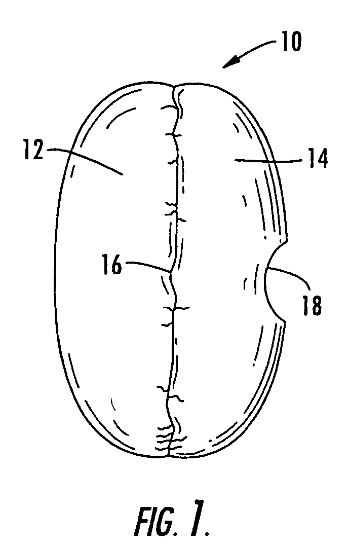
[0020]FIG. 1 illustrates a typical driver side air bag 10 that may be constructed of fabric made according to the present invention. Air bag 10 includes a front panel 12 which is attached to a back panel 14 along a seam line 16. Back panel 14 defines an inflator hole 18 to provide fluid communication with a source of inflation gas. It should be appreciated that other types of air bags could also be constructed using the fabric of the present invention, such as passenger side, side cushion and side curtain air bags. Moreover, the present invention could be applied to both cut and sewn air bags or to one-piece-woven air bags (where sewing is not required).
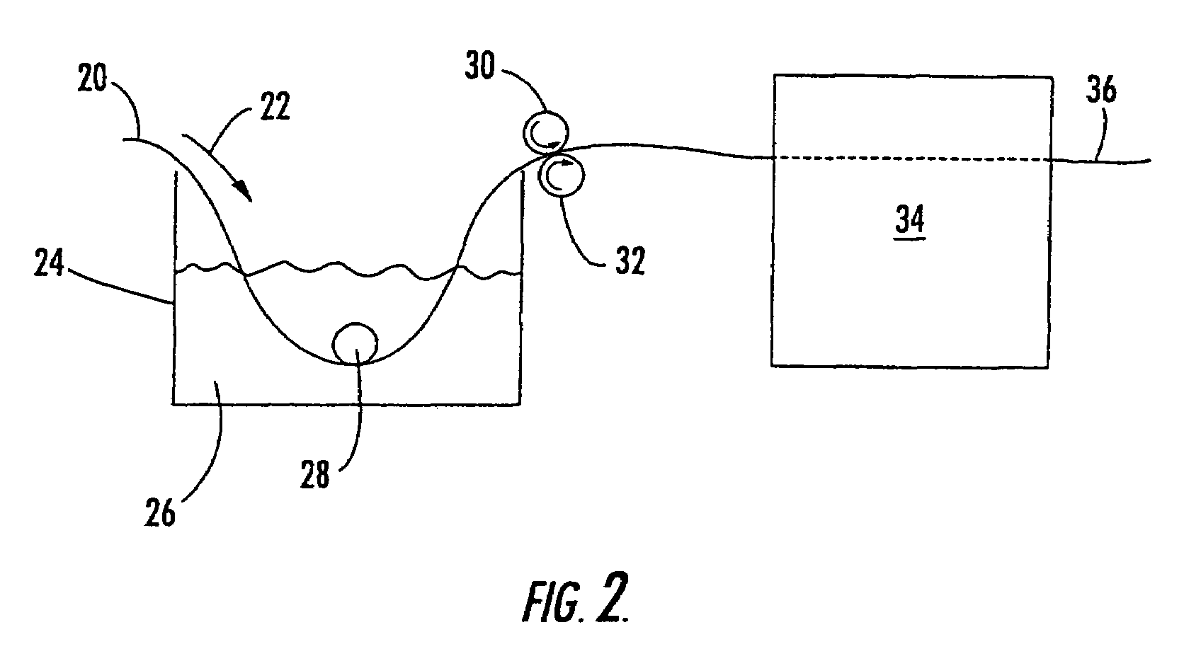
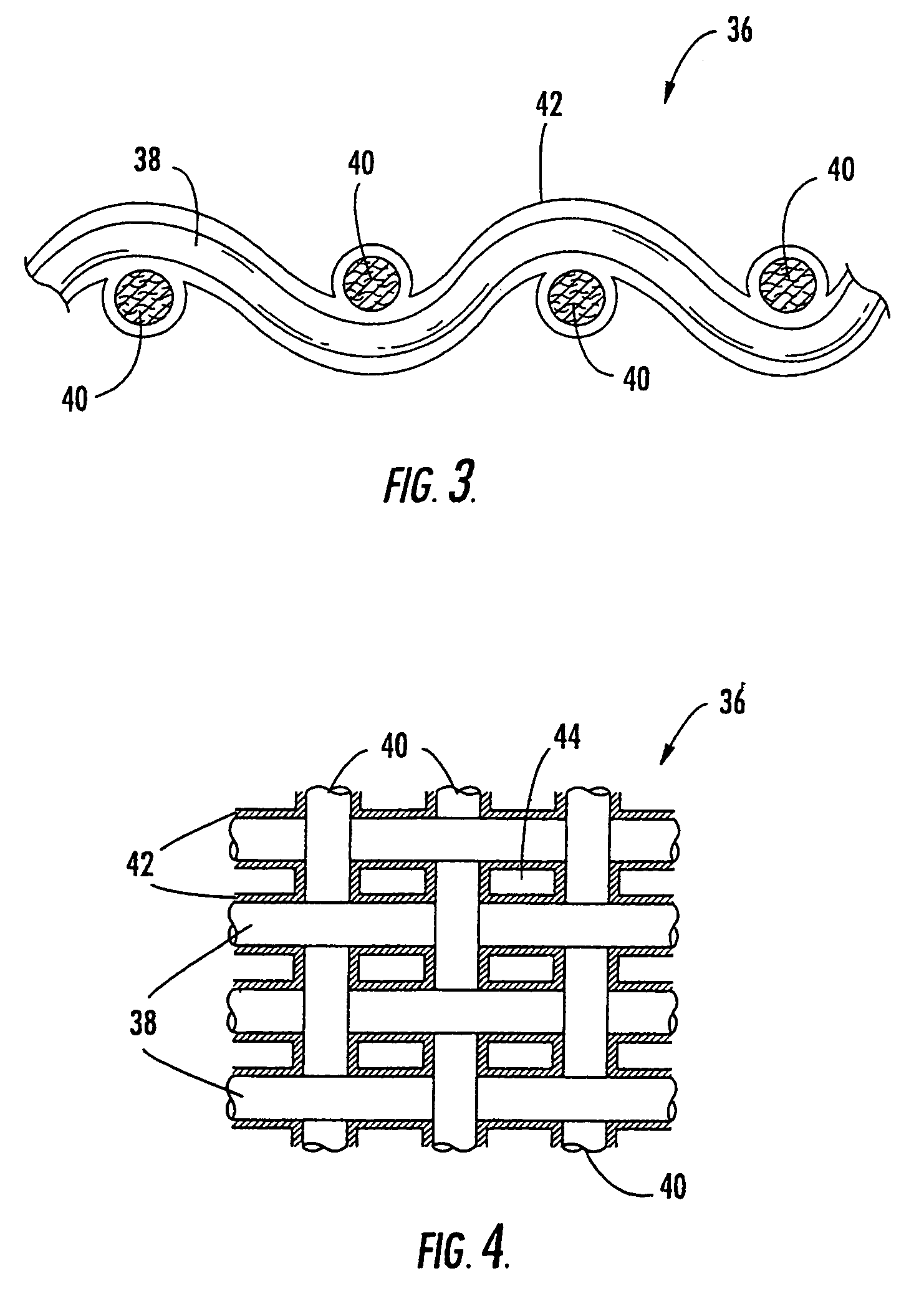
[0021]Referring to FIGS. 2, 3 and 4, the fabric of...
PUM
| Property | Measurement | Unit |
|---|---|---|
| Linear density | aaaaa | aaaaa |
| Linear density | aaaaa | aaaaa |
| Linear density | aaaaa | aaaaa |
Abstract
Description
Claims
Application Information