Variable coolant pump

Inactive Publication Date: 2011-07-07
SCHAEFFLER TECH AG & CO KG
View PDF9 Cites 24 Cited by
  • Summary
  • Abstract
  • Description
  • Claims
  • Application Information

AI Technical Summary

Benefits of technology

[0014]According to a further configuration of the invention, the hollow shaft is mounted by means of a double-row ball bearing. A reliable mounting of the hollow shaft with good load capacity is thereby achieved.
[0015]In a development of the invention, the pulley and the positioning unit are placed in a chamber

Problems solved by technology

A disadvantage of such an arrangement is that the system for regulating the coolant flow by means of the slide element involves a complex and costly mechanism and therefore a complicated structure.
Mo

Method used


Image

  • Variable coolant pump
  • Variable coolant pump
  • Variable coolant pump

Examples


Example

DETAILED DESCRIPTION OF THE DRAWINGS

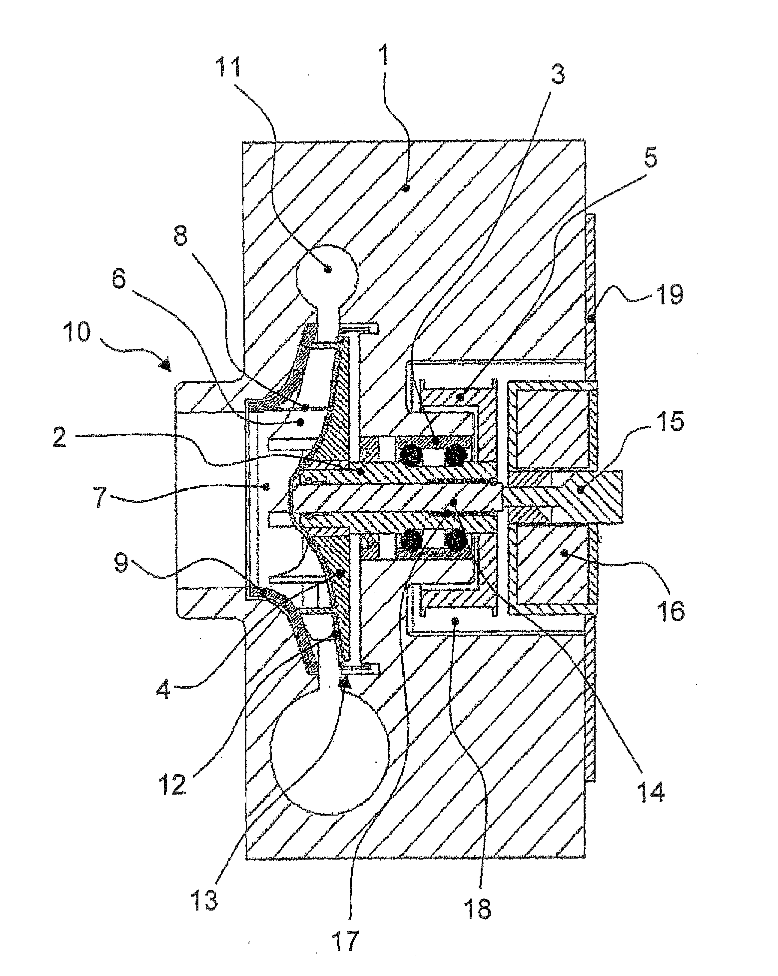
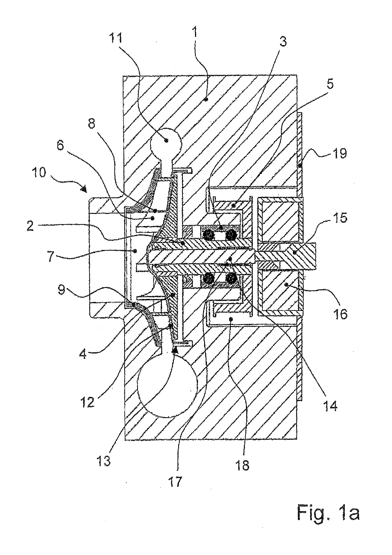
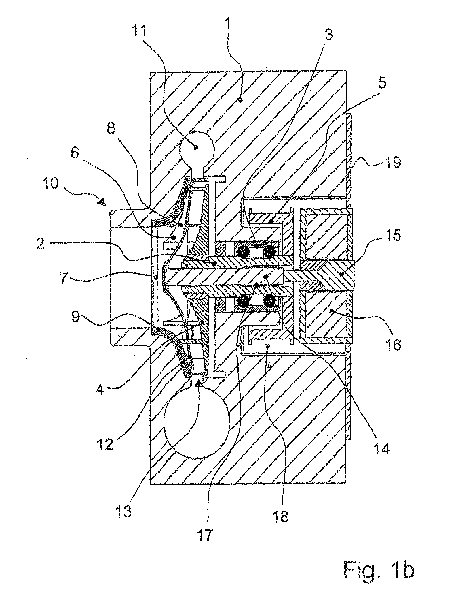
[0020]FIG. 1a shows a sectional view of the coolant pump according to the invention, which has a hollow shaft 2 mounted in a pump housing 1. This hollow shaft 2 is mounted rotatably via a double-row ball bearing 3 in a bore of the pump housing 1 and carries an impeller 4 on its one end while it is connected rigidly to a pulley 5 at its other end. The hollow shaft 2 is driveable via this pulley 5 by means of a belt drive (not shown here) of the internal combustion engine. The impeller 4 has vanes 6 which extend axially into an inlet chamber 7 of the coolant pump. The impeller 4 is further connected via axial bridges 8 to a cover disc 9. During operation of the coolant pump water is drawn into the inlet chamber 7 via an inlet connection piece 10 of the pump housing 1 through rotation of the impeller 4 together with the cover disc 9 and, as a result of the centrifugal forces generated by the impeller 4 and further intensified by the vanes 6, is force...


PUM


Abstract

A variable coolant pump for a cooling circuit of an internal combustion engine, that has a pump housing in which is mounted a hollow shaft that is driveable by a pulley. At one end of the hollow shaft an impeller is fastened which has vanes projecting into an inlet chamber and which is firmly connected via axial bridges to a cover disc. Through rotation of the impeller together with the cover disc, water can be sucked into the inlet chamber via an inlet connection piece of the pump housing and conveyed by the vanes into an annular passage of the pump housing. A guide disc with a contour corresponding to the impeller is further arranged between impeller and cover disc. The guide disc is guided by the axial bridges and can be displaced axially via a positioning unit by a piston located inside the hollow shaft.

Description

FIELD OF THE INVENTION[0001]The invention relates to a variable coolant pump for a cooling circuit of an internal combustion engine, comprising a pump housing in which is mounted a hollow shaft driveable by means of a pulley, at the one end of which hollow shaft is fastened an impeller which has vanes projecting into an inlet chamber and which is firmly connected via axial bridges to a cover disc, it being possible through rotation of the impeller together with the cover disc for water to be sucked into the inlet chamber via an inlet connection piece of the pump housing and to be conveyed by means of the vanes into an annular passage of the pump housing.BACKGROUND OF THE INVENTION[0002]In the field of internal combustion engines, water-cooled engines have been adopted very extensively. In such engines cooling water is pumped in a closed circuit with the aid of a coolant pump through cooling passages in the region of the cylinders in order to cool the internal combustion engine, and ...

Claims


Application Information

Patent Timeline
IPC IPC(8): F01P5/10
CPCF04D15/0038F05D2270/62
Inventor DRAHEIM, ALEXANDERNENDEL, ANDREASGOLOVATAI-SCHMIDT, EDUARDSCHAEFER, JENSSCHAEFER, SANDRA
Owner SCHAEFFLER TECH AG & CO KG
Why Eureka
Try Eureka