
In-wheel electric motor provided with an inverter and method of manufacturing such an in-wheel electric motor

Pending Publication Date: 2020-05-28
E TRACTION EURO BV
View PDF6 Cites 0 Cited by
  • Summary
  • Abstract
  • Description
  • Claims
  • Application Information

AI Technical Summary

Benefits of technology

The invention is a power electronics device that can be easily inserted or removed from an electric motor without the need for disassembly of the vehicle's drive wheel. The device has a connector member and a casing, with the two connected by plugs and sockets. This simplifies the placement of the device within the drive wheel assembly. The connector member has parallel protruding elements and the casing has corresponding recesses, making mounting easier. The technical effect of this invention is that it saves time for installation and de-installation during maintenance, and makes mounting within the drive wheel assembly easier and more convenient.

Problems solved by technology

A disadvantage of the prior art in-wheel electric motor is that repair or replacement of the power electronics requires that the housing is opened and largely removed.

Method used


Image

  • In-wheel electric motor provided with an inverter and method of manufacturing such an in-wheel electric motor
  • In-wheel electric motor provided with an inverter and method of manufacturing such an in-wheel electric motor
  • In-wheel electric motor provided with an inverter and method of manufacturing such an in-wheel electric motor

Examples


Embodiment Construction

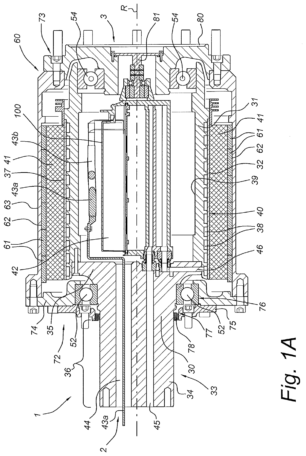
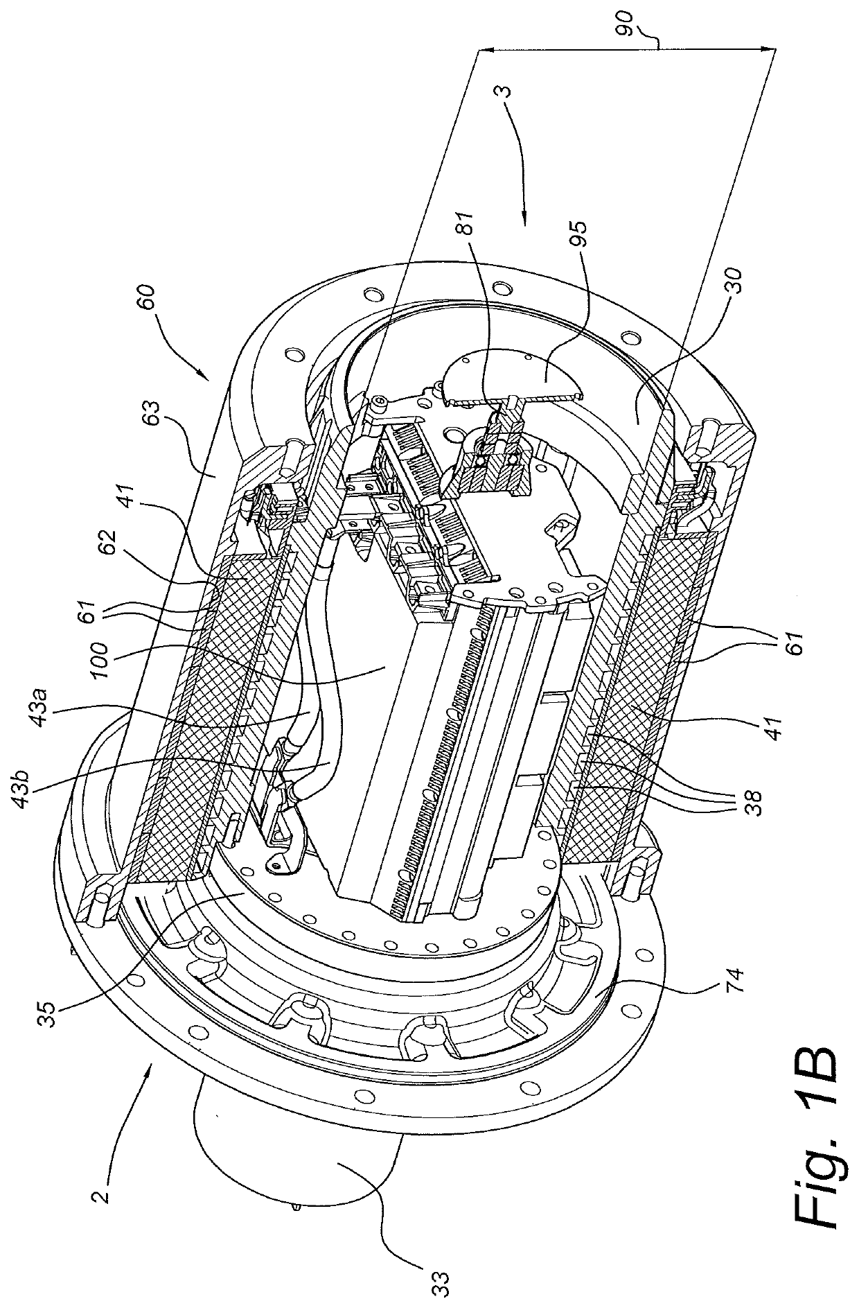
[0028]FIG. 1A shows a cross-sectional view of a drive assembly 1 for use with the present invention. The drive assembly comprises a stator 30 with a hollow stator body 31 which has an outer surface 32 around which a rotor 60 is arranged. The drive assembly further comprises an axle stub or connector stub 33, arranged at a vehicle side 2 of the assembly 1 for attaching the drive assembly to the vehicle. The connector member 33 is fixedly connected to the stator body 34 via a flange 35 which lies within the rotor 60 and has a larger diameter than a portion 36 of the axle stub 33 which lies outside the peripheral outer surface 63 of the rotor 60. For supporting rotational movement of the rotor 60 around the axis of rotation R, vehicle side bearings 52 are provided via which the rotor supported on the stub 33 on the vehicle side. On the road side 3, the rotor is rotatingly supported on the stator body 31 via road side bearings 54.

[0029]A plurality of permanent magnets 61 is attached on ...


PUM


Abstract

An in-wheel electric motor includes a stator with at a vehicle side an connector member, a cylindrical hollow stator body connected to the connector member; an outer surface of the stator body being equipped with stator windings, and further including a cylindrical rotor body coaxially enclosing the stator; the electric motor further including a power electronics device for powering the stator windings, wherein the hollow stator body is provided with a stator body opening at a road side of the electric motor for receiving the power electronics device, and the enclosing rotor body is provided with a removable cover plate covering a rotor body opening of the rotor body at the road side and covering the stator body opening.

Description

FIELD OF THE INVENTION[0001]The present invention relates to a method of assembling an in-wheel electric motor. Also, the invention relates to an in-wheel electric motor. Furthermore, the invention relates to a drive assembly for a wheel of a vehicle comprising such an electric motor.BACKGROUND[0002]Such an in-wheel electric motor is known from WO 2013 / 025096 that describes an electric vehicle with an in-wheel electric motor in which the rotor is coupled to a rim of the wheel carrying one or more tyres. The stator is mounted on the frame of the vehicle via a wheel suspension system. The known in-wheel motor is part of a direct drive wheel in which the electromagnets of the motor directly drive the rim and the tyre without any intermediate gears. In this manner, weight and space are saved and the number of components in the drive assembly is minimized.[0003]The torque that is generated by the in-wheel motor depends on the flux-carrying surface between the rotor and the stator and is ...

Claims


Application Information

Patent Timeline
IPC IPC(8): B60K7/00H02K11/33H02K29/06H02K9/197H02K1/18H02K7/14
CPCB60L2240/36H02K9/197H02K11/33B60L2220/44H02K29/06H02K7/14H02K1/187B60K7/0007Y02T10/64H02K7/006H02K5/203H02K5/10H02K7/06H02K11/21
Inventor VAN DER WAL, REINHARD PETERVAN SEVENTER, TIMOTHY
Owner E TRACTION EURO BV
Learn More