Copulsation milking system

a milking system and vacuum technology, applied in the field of vacuuming milking systems, can solve problems such as unnecessary noise, and achieve the effect of reducing the impact and associated nois

Inactive Publication Date: 2011-07-14
GEHM LANNY +1
View PDF9 Cites 11 Cited by
  • Summary
  • Abstract
  • Description
  • Claims
  • Application Information

AI Technical Summary

Benefits of technology

[0011]An improved milking system that features a compressible means of limiting travel of a solenoid valve plunger. The system comprises a two-valve control that provides a sharp transition between the alternating air pressure and vacuum that are supplied to a teat cup. One valve of the pulsator mechanism controls the vacuum inlet; the other valve controls the atmospheric air inlet. Each valve device has a seal at one end and a compressible member between the valve device and the solenoid valve stopping feature. The compressible material provides a means of reducing the impact and associated noise.

Problems solved by technology

This impact also creates unnecessary noise.

Method used


Image

  • Copulsation milking system
  • Copulsation milking system

Examples


Embodiment Construction

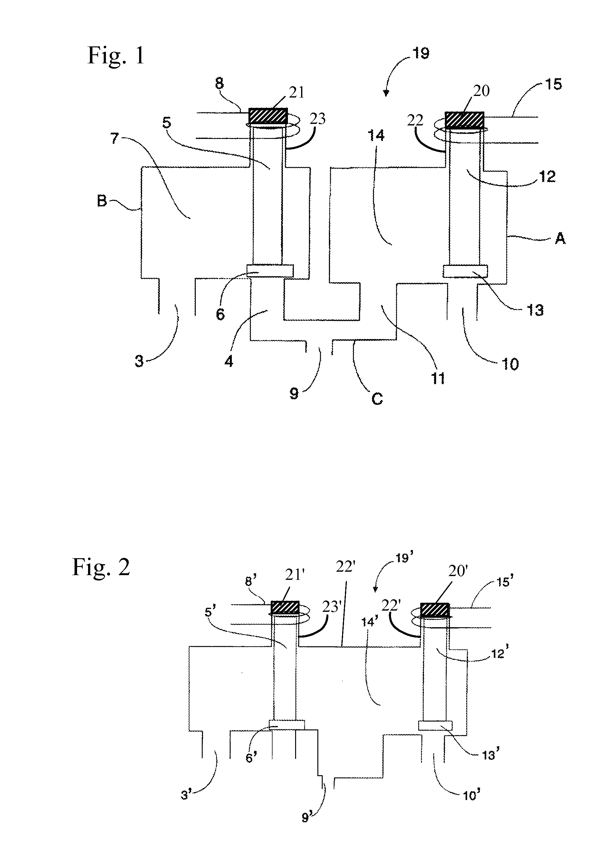
[0014]The invention pertains to a milking system having a pulsator unit that has separate pressure and vacuum channels. Each channel is controlled by its own respective valve. The first valve of channel A controls the vacuum inlet, controlling the supply of a vacuum to a teat-cup of a milking apparatus. The second valve of channel B controls the atmospheric air inlet and air pressure to a teat cup of a milking apparatus. The electronics actuating the valves creates a sharp transition in the pulsator outlet between the atmospheric air and the vacuum, so that the vacuum and atmospheric air sources are never simultaneously connected.

[0015]Referring to FIG. 1, a pulsator 19 includes three channels, A, B and C, with channel A controlling the vacuum inlet 10, and channel B controlling the atmospheric air pressure inlet 3. Channel A has a chamber 14, and channel B has a chamber 7. Chamber 14 has a vacuum pressure outlet 11 and a vacuum pressure inlet 10. Chamber 7 comprises an atmospheric ...


PUM


Abstract

There is provided a method for improving the reliability and performance of a valve device that transitions between the pressure and vacuum phases for the purpose of milking animals. The improvement reduces physical wear of the movable parts within the valve device while ensuring proper function of said movable parts.

Description

BACKGROUND OF THE INVENTION[0001]1. Field of the Invention[0002]The present invention pertains to an improvement of a milking system for domesticated animals and, more particularly to a milking system with two independent valves for alternating between the pressurizing and vacuum cycles of the teat cup, as well as electronic controls for independently actuating the atmospheric pressure and vacuum cycles.[0003]2. Description of Related Art[0004]Typical milking systems apply periodic alternating pressure to the teat cup of a milking apparatus. This results in the removal and the flow of milk from the udder to which the teat cup is applied. The alternating pressure between the atmospheric pressure and vacuum cycles is controlled by a two-way valve combination that feeds a pulsation chamber. Conventional pulsator designs incorporate a sealing feature at both ends to provide proper function for minimizing air or vacuum leakage. This valving apparatus is commonly referred to as a pulsator...

Claims


Application Information

Patent Timeline
Patent Type & Authority Applications(United States)
IPC IPC(8): A01J5/14A01J5/02
CPCA01J5/14
Inventor GEHM, LANNYGEHM, WILLIAM
Owner GEHM LANNY
Why Eureka
Try Eureka