Fuel supply device and fuel supply method

Active Publication Date: 2011-07-14
YANMAR POWER TECHNOLOGY CO LTD
View PDF7 Cites 9 Cited by
  • Summary
  • Abstract
  • Description
  • Claims
  • Application Information

AI Technical Summary

Benefits of technology

[0014]In accordance with this configuration, since the circulating means circulates the oil mixture that has been heated by the exhaust heat of the drive source such as an engine, the oil mixture supplied to the drive source is heated further. This raises the content ratio of the high viscosity fuel oil among the fuel oils in the oil mixture.
[0015]The fuel supply apparatus preferably further includes a plurality of fuel tanks each storing different one of the fuel oils, and flow regulating means located between the fuel tanks and the oil mixture generating means. The flow regulating means regulates the flow rate of each fuel oil so as to supply the plurality of types of fuel oils to the mixing means, and controls the mixture ratios of the oil mixture.
[0016]In accordance with this configuration, the mixture ratios of the oil mixture can be controlled with a simple structure, by adjusting the flow rate of the fuel oils.
[0017]In accordance with a second aspect of the present invention, a fuel supply method using a fuel supply

Problems solved by technology

However, in general, biodiesel fuel is easily oxidized and degraded by heat.
Therefore, use of such an oil mixture as fuel c

Method used


Image

  • Fuel supply device and fuel supply method
  • Fuel supply device and fuel supply method
  • Fuel supply device and fuel supply method

Examples


Example

[0024]One embodiment of the present invention will now be described with reference to the drawings.

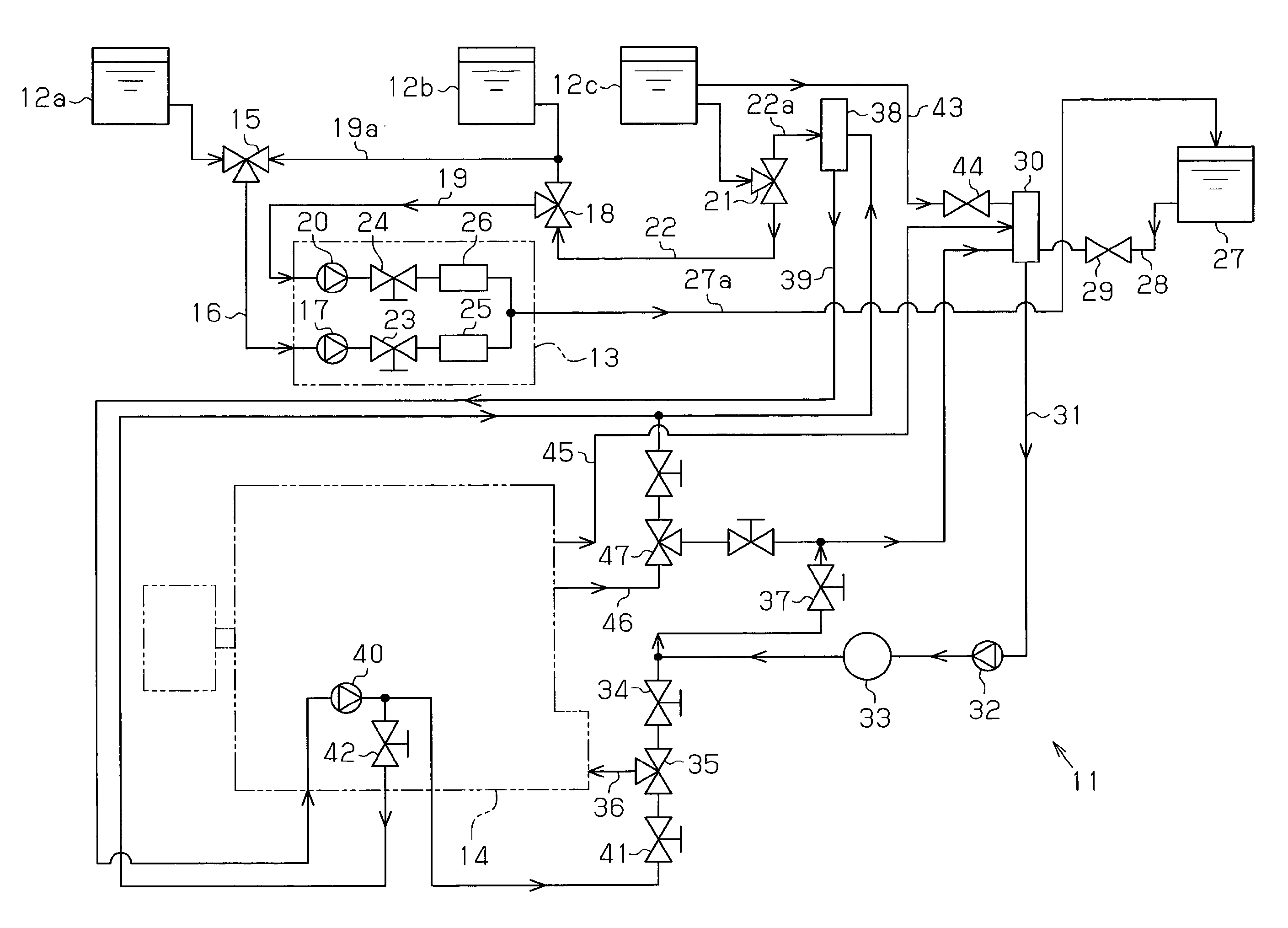
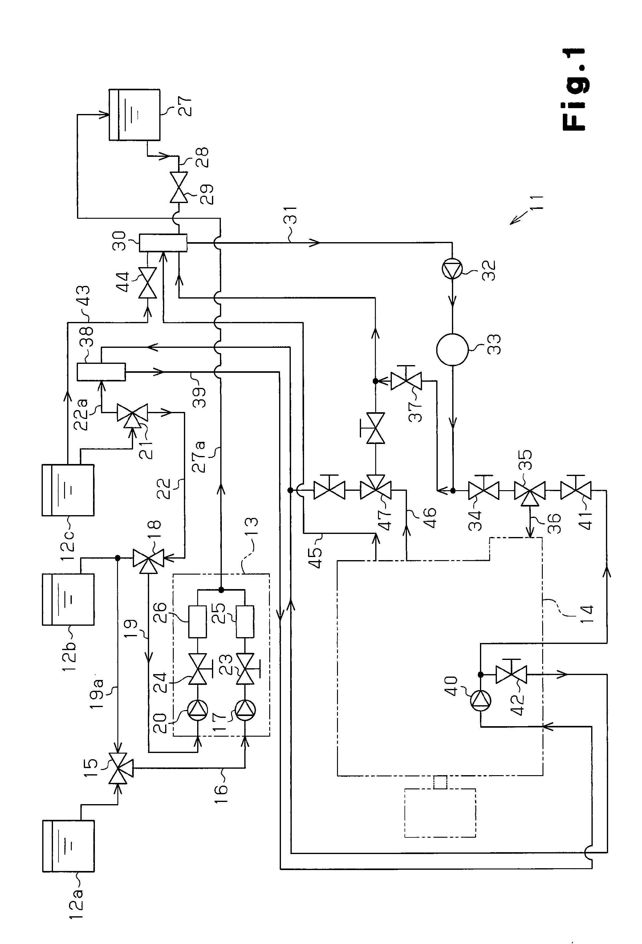
[0025]As shown in FIG. 1, a fuel supply apparatus 11 according to the present embodiment includes first to third fuel tanks 12a, 12b, 12c, a blender 13, and an engine 14 serving as a drive source. The first to third fuel tanks 12a, 12b, 12c store, as fuel oils, a vegetable oil, a fatty acid methyl ester, and an A heavy oil, respectively. The blender 13 functions as mixing means for mixing fuel oils sent from the fuel tanks 12a, 12b, 12c. The engine 14 receives and is driven by the oil mixture mixed by the blender 13. Among the fuel oils, the vegetable oil stored in the first fuel tank 12a and the fatty acid methyl ester stored in the second fuel tank 12b are non-heat resistant fuel oils, while the A heavy oil stored in the third fuel tank 12c is a heat resistant fuel oil. The non-heat resistant fuel oil refers to a fuel oil that is highly likely to be oxidized and degraded when directl...


PUM


Abstract

Mixture ratios of fuel oils, which are arbitrarily combined and mixed to generate an oil mixture, are set to be mixture ratios that satisfy a predetermined viscosity condition. Based on the mixture ratios, a CPU (49) generates an oil mixture by controlling flow regulating valves (23, 24) in a blender (13). When the oil mixture is supplied to the engine (14) as a pressurizing pump (32) operates, the viscosity is detected by a viscometer (33). The CPU (49) adjusts the mixture ratios based on the detection result, such that the viscosity of the oil mixture satisfies the viscosity condition and that the content of a fuel oil having the highest viscosity among the fuel oils in the oil mixture is maximized.

Description

TECHNICAL FIELD[0001]The present invention relates to a fuel supply apparatus and a fuel supply method for supplying as fuel an oil mixture made by mixing various types of oils.BACKGROUND ART[0002]In recent years, the increase in performance of diesel engines has enabled oil mixture to be used as fuel other than light oils or heavy oils, which are used alone. The oil mixture refers to a type of oil made by mixing multiple types of oils having different viscosities. Accordingly, inexpensive low-quality oil having a viscosity higher than that of high-quality oil such as light oil has been selected as a material of the oil mixture. This reduces fuel costs.[0003]For such an oil mixture, not only oils having low viscosities, but also oils having high viscosities are used as materials, taking into consideration the prices of the fuels. To use oil mixture as fuel, the viscosity of the oil mixture itself is adjusted. For example, Patent Document 1 discloses a fuel supply apparatus for suppl...

Claims


Application Information

Patent Timeline
IPC IPC(8): F02D19/08F02M37/00
CPCF02D19/0628F02D19/0684F02D19/081F02D41/0025F02D19/0652Y02T10/36F02D19/0634F02D19/0665F02D19/0676F02D2200/0612Y02T10/30
Inventor YAGI, YUKIOTYUN, I HONOOTOMO, YUUKI
Owner YANMAR POWER TECHNOLOGY CO LTD
Why Eureka
Try Eureka