Direct drive wind turbine and blade assembly

a direct drive, wind turbine technology, applied in the direction of magnetic circuit rotating parts, electric generator control, magnetic circuit shape/form/construction, etc., can solve the problems of increasing deployment costs, unfavorable use of wind turbines in more of a residential and rural setting, and unduly shortening the service life of wind turbines, so as to reduce cogging torque reduce cogging torque

Inactive Publication Date: 2011-07-14
TODOROF BILL
View PDF14 Cites 48 Cited by
  • Summary
  • Abstract
  • Description
  • Claims
  • Application Information

AI Technical Summary

Benefits of technology

[0018]Thus, the primary feature or advantage of the present invention is an improved wind turbine and blade assembly for direct drive (gearless) wind turbines.
[0019]One or more of these and / or other features or advantages of the present invention will become apparent from the specification and claims that follow.BRIEF SUMMARY OF THE INVENTION
[0020]One or more of the foregoing features or advantages may be achieved by a direct drive wind turbine driven by a blade assembly. The direct drive wind turbine includes a frame enclosed by a housing, a shaft rotatably supported by the frame, a magnet array attached to and arranged circumferentially about an inner wheel attached to the shaft so that each magnet is angled relative to the inner wheel to reduce cogging torque, a transformer array arranged circumferentially about an outer wheel attached to the frame, and the inner wheel being rotated within and relative to the outer wheel to produce electricity. In a preferred form, the direct drive wind turbine includes each magnet being angled between 5-45 degrees, more specifically at between 8 and 16 degrees, and optimally at 15 degrees, relative to a line perpendicular to opposing outer peripheral edges of the inner wheel to reduce cogging torque.
[0021]In yet another aspect of the present invention, a direct drive wind turbine is disclosed. The wind turbine includes a shaft rotatably supported by a frame, a magnet array attached to and arranged circumferentially about an inner wheel attached to the shaft, a transformer array attached to and arranged circumferentially on an outer wheel attached to the frame, a blade assembly having a plurality of blades where each blade is attached to a plug coupled within a socket attached to a blade hub attached to the shaft, and a tensioning means is enclosed within the socket and configured to act on the plug to resist movement of the blade out of the wind from a neutral position facing into the wind. In a preferred form, the tensioning means is calibrated to automatically adjust blade pitch relative to the speed of the wind acting on the blades so that the blades automatically rotate out of the wind from the neutral position under the force of the wind as wind speed increases.
[0022]According to another aspect of the present invention, a new method for generating electricity using a direct drive wind turbine is disclosed. The method includes the steps of: providing a frame enclosed by a housing, a shaft rotatably supported by the frame, a magnet array attached to and arranged circumferentially about an inner wheel attached to the shaft, and a transformer array arranged circumferentially about an outer wheel attached to the frame; angling the magnets relative to the inner wheel; and rotating the inner wheel within and relative to the outer wheel to produce electricity. In a preferred form, the method includes angling each magnet is angled between 5-45 degrees relative to a line perpendicular to opposing outer peripheral edges of the inner wheel to reduce cogging torque.
[0023]According to still another aspect of the present invention, a method for generating electricity using a direct drive wind turbine is disclosed. The method includes the steps of: providing a shaft rotatably supported by a frame, a magnet array attached to and arranged circumferentially about an inner wheel attached to the shaft, a transformer array attached to and arranged circumferentially on an outer wheel attached to the frame, and a blade assembly comprising a plurality of blades so each blade is attached to a plug coupled within a socket attached to a blade hub attached to the shaft; resisting rotation of the blades away from a neutral position with a tensioning means enclosed within the socket; and rotating the inner wheel within and relative to the outer wheel to produce electricity. In a preferred form, the method also includes the steps of: urging the blades back to the neutral position using the tensioning means; and self-tuning the blades by automatically and instantaneously rotating out of the wind away from said neutral position under the force of and relative to the wind speed.

Problems solved by technology

Although large-scale wind turbines work well for harvesting electricity on commercial and industrial scales, these wind turbines are not amenable to use in more of a residential and rural setting.
Because of the heat generated, especially in wind turbines that use gearing systems to operate at multiple speeds, and the combination of usage and environmental factors that can lead to system failure, whether by excessive winds, intense ambient heat or other elements, and the wear on the blades and experienced by moving parts within the wind turbine, the service life of the wind turbine may be unduly shortened, with increased deployment costs particularly as the turbines servicing requirements increase or the useful life of the turbine is shortened.
Many of these turbines, including smaller scale wind turbines, require large amounts of wind energy to start the rotation of the blade assembly by breaking the cogging torque generated by a magnetic flux density within the wind turbine assembly.
In addition to the desire to increase blade efficiency, it is well known in the art of wind turbines that the blade assembly can experience catastrophic forces from excessive or high-velocity winds, thereby causing failure of the blade assembly and wind turbine.
This type of turbine design unnecessarily requires the added expense of wind diagnostics and analysis hardware or systems to assess the wind and then provide correction to the angle of the blades.
These current apparatuses and methods that use added electromechanical control systems for blade rotation require an increased parts count with increased service requirements and multiple points of failure.

Method used


Image

  • Direct drive wind turbine and blade assembly
  • Direct drive wind turbine and blade assembly
  • Direct drive wind turbine and blade assembly

Examples


Embodiment Construction

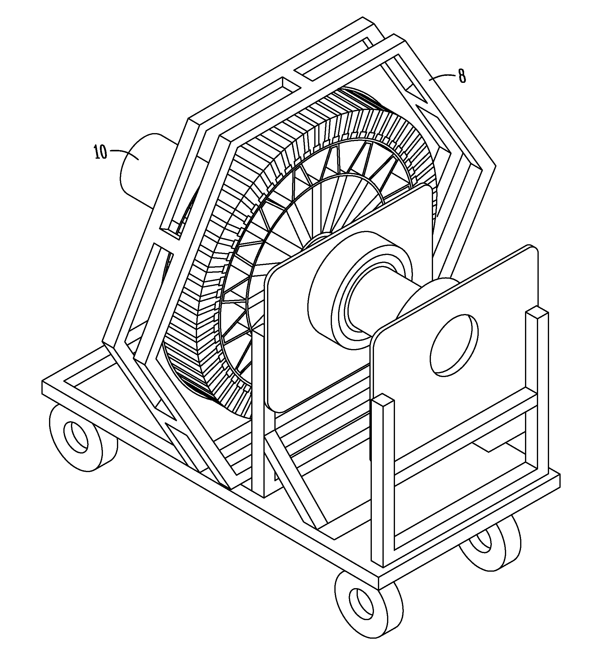
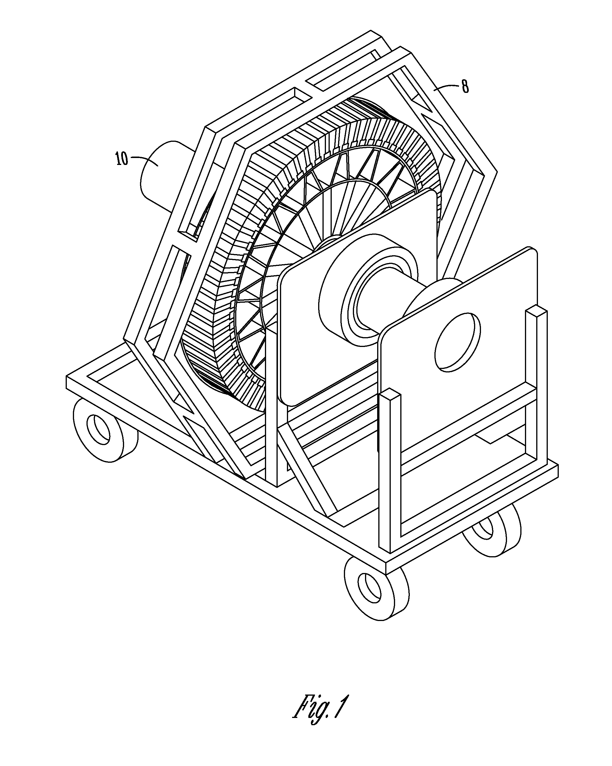
[0030]FIGS. 1 and 2 illustrate an isometric view of the electrical generating component of the wind turbine assembly according to an exemplary embodiment of the present invention. For purposes of illustration and even demonstration, the electrical generating component of the wind turbine assembly is shown mounted to a portable cart 8. The electrical generating component of the wind turbine assembly can take on various operational configurations as the design of the component is truly scalable up or down based on the desired electrical output.

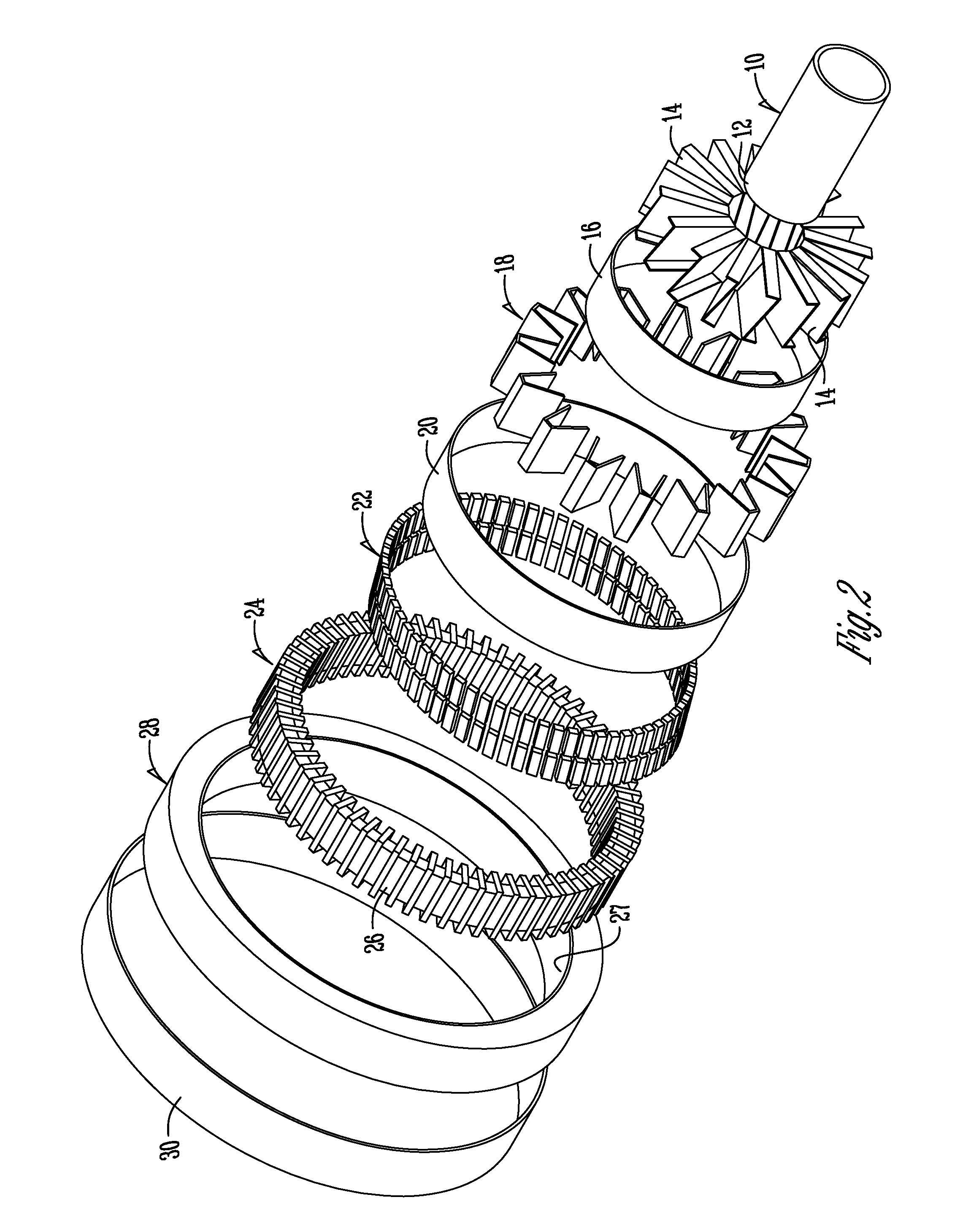
[0031]FIGS. 1-6 illustrate the various possible components and configurations for the wind turbine assembly. Each of the possible components for one embodiment of the wind turbine assembly is best illustrated in the exploded and sectional views shown in FIGS. 2 and 3.

[0032]The basic structure of the wind turbine assembly, according to an exemplary embodiment of the present invention, has a central shaft 10 connecting the blade assembly to the wi...


PUM


Abstract

Apparatuses and methods for an improved wind turbine and blade assembly are disclosed. The wind turbine has a wind turbine assembly being rotatably driven by the blade assembly. The wind turbine assembly has a shaft connected to an inner wheel by a supporting structure. A magnet array is disposed circumferentially about the inner wheel. A transformer array is disposed circumferentially about an outer wheel. The shaft rotates the inner wheel with the magnet array within the outer wheel having the transformer array for producing electricity. Magnets within the array are angled relative to the inner wheel to reduce the cogging torque. Blades are held in a neutral position into the wind by tensioning means, which resists rotation of the blades out of the wind to tune the blades to the wind velocity.

Description

CROSS REFERENCE TO RELATED APPLICATION[0001]This application is a Continuation application of U.S. Ser. No. 12 / 130,600 filed May 30, 2008, which claims priority under 35 U.S.C. §119 to provisional application Ser. No. 60 / 941,565 filed Jun. 1, 2007, herein incorporated by reference in their entirety.FIELD OF THE INVENTION[0002]This invention relates to a wind turbine. Specifically, this invention relates to an improved wind turbine and blade assembly for direct drive (gearless) wind turbines.BACKGROUND OF THE INVENTION[0003]It is known that energy farming and production using renewable resources is becoming increasingly important as the costs of nonrenewable fuels such as fossil fuels continue to rise, and earth's nonrenewable resources are depleted more and more each day. It can also be appreciated that harvesting wind energy in residential and rural settings for powering energy needs for such activities that occur in residential and rural settings are beneficial in addition to comm...

Claims


Application Information

Patent Timeline
Patent Type & Authority Applications(United States)
IPC IPC(8): F03D9/00F03D7/00
CPCF03D1/00F03D1/06F03D9/002F05B2220/7066F05B2280/5008F16C2360/31H02K21/145H02K2201/06Y02E10/721Y02E10/725H02K7/1838H02K1/30F03D9/25F03D13/10F03D80/60Y02E10/72
Inventor TODOROF, BILL
Owner TODOROF BILL
Why Eureka
Try Eureka