Flow Separation for Stereo Visual Odometry

a flow separation and stereo visual odometry technology, applied in image analysis, image enhancement, instruments, etc., can solve problems such as low processing efficiency, high computational requirements, and inability to provide optimal ransac,

Inactive Publication Date: 2011-07-14
GEORGIA TECH RES CORP
View PDF13 Cites 27 Cited by
  • Summary
  • Abstract
  • Description
  • Claims
  • Application Information

AI Technical Summary

Problems solved by technology

For example, one system employs an image-based approach that has high computational requirements and is not suitable for high frame rates.
Large-scale visual odometry in challenging outdoor environments has been attempted, but has a problem handling degenerate data.
Most current visual odometry systems use the random sample consensus (RANSAC) algorithm for robust model estimation, and are therefore susceptible to problems arising from nearly degenerate situations.
RANSAC generally fails to provide an optimal result when directly applied to nearly degenerate data.
In visual odometry nearly degenerate data occurs for a variety of reasons, such as when imaging ground surfaces with low texture, imaging in bad lighting conditions that result in overexposure, and motion blur due to movement of either the platform or objects being imaged.

Method used


Image

  • Flow Separation for Stereo Visual Odometry
  • Flow Separation for Stereo Visual Odometry
  • Flow Separation for Stereo Visual Odometry

Examples


Embodiment Construction

[0019]A preferred embodiment of the invention is now described in detail. Referring to the drawings, like numbers indicate like parts throughout the views. Unless otherwise specifically indicated in the disclosure that follows, the drawings are not necessarily drawn to scale. As used in the description herein and throughout the claims, the following terms take the meanings explicitly associated herein, unless the context clearly dictates otherwise: the meaning of “a,”“an,” and “the” includes plural reference, the meaning of “in” includes “in” and “on.”

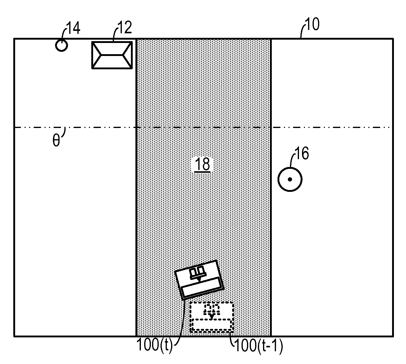
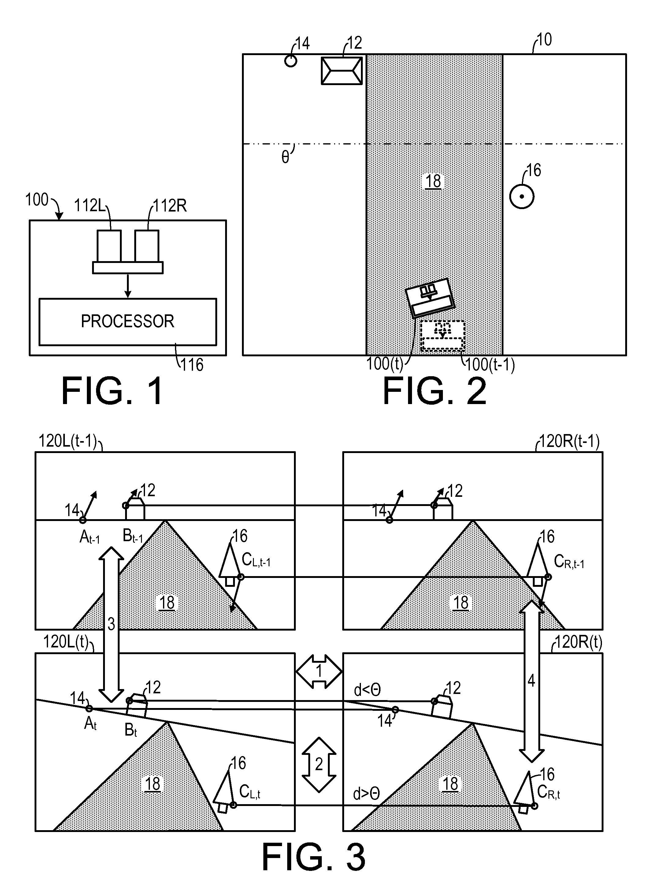
[0020]As shown in FIG. 1, one embodiment operates on a processor 116 that is associated with a mobile platform 100, such as a robot. The processor 116 is in communication with a left camera 112L and a right camera 112R, that form a stereo camera pair. (It should be noted that other types of stereographic sensors could be employed. Such sensors could include, for example, directional sound sensors, heat sensors and the like.) As shown i...


PUM


Abstract

In a method for determining a translation and a rotation of a platform, at least a first frame and a previous frame are generated. Points are matched between images generated by two stereoscopic sensors. Points are matched to corresponding stereo feature matches between two frames, thereby generating a set of putative matches. Putative matches that are nearer to the platform than a threshold are categorized as near features. Putative matches that are farther to the platform than the threshold are categorized as distance features. The rotation of the platform is determined by measuring a positional change in two of the distant features. The translation of the platform is determined by compensating one of the near features for the rotation and then measuring a change in one of the near features measured between the first frame and the second frame.

Description

CROSS-REFERENCE TO RELATED APPLICATION(S)[0001]This application claims the benefit of U.S. Provisional Patent Application Ser. No. 61 / 249,805, filed Oct. 8, 2009, the entirety of which is hereby incorporated herein by reference.STATEMENT OF GOVERNMENT INTEREST[0002]This invention was made with government support under contract No. FA8650-04-C-7131, awarded by the United States Air Force. The government has certain rights in the invention.BACKGROUND OF THE INVENTION[0003]1. Field of the Invention[0004]The present invention relates to video processing systems and, more specifically, to a video processing system used in stereo odometry.[0005]2. Description of the Related Art[0006]Visual odometry is a technique that estimates the egomotion (the motion of the platform on which sensors, such as cameras, used to determine the motion are mounted) from images perceived by moving cameras. A typical use is autonomous navigation for mobile robots, where getting accurate pose estimates is a cruc...

Claims


Application Information

Patent Timeline
Patent Type & Authority Applications(United States)
IPC IPC(8): H04N13/02G06K9/00
CPCG06T7/2033G06T2207/30244G06T7/2086G06T7/246G06T7/285
Inventor DELLAERT, FRANKKAESS, MICHAELNI, KAI
Owner GEORGIA TECH RES CORP
Why Eureka
Try Eureka