

Electronic device
a technology of electronic devices and circuit boards, applied in the direction of electrical apparatus, electrical apparatus, electrical apparatus contruction details, etc., can solve the problems of increasing production costs, restricting the use of parts, complex wiring, etc., and achieve the effect of increasing the data transfer rate between the circuit board units
- Summary
- Abstract
- Description
- Claims
- Application Information
AI Technical Summary
Benefits of technology
Problems solved by technology
Method used
Image

Examples
first embodiment
A. First Embodiment
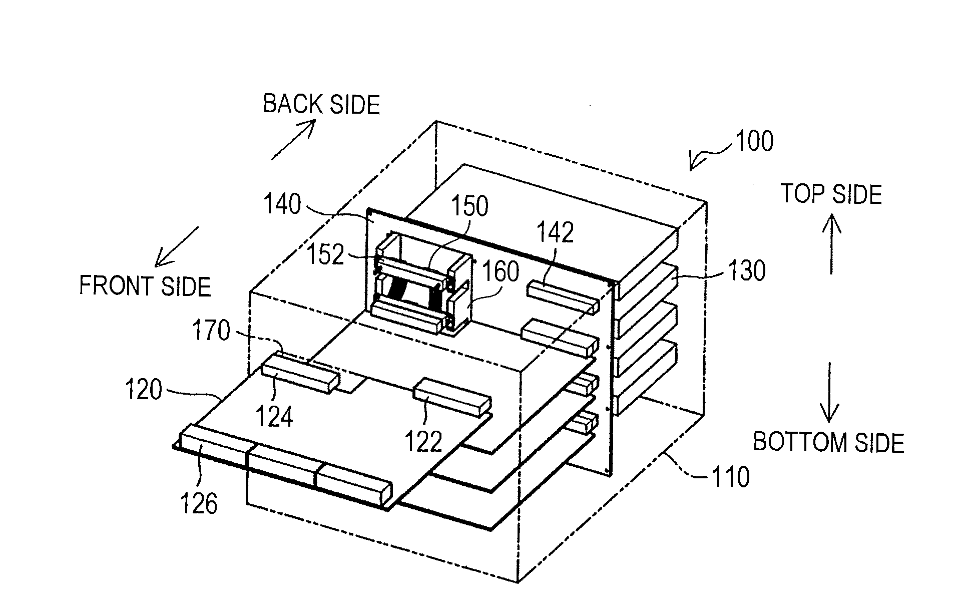
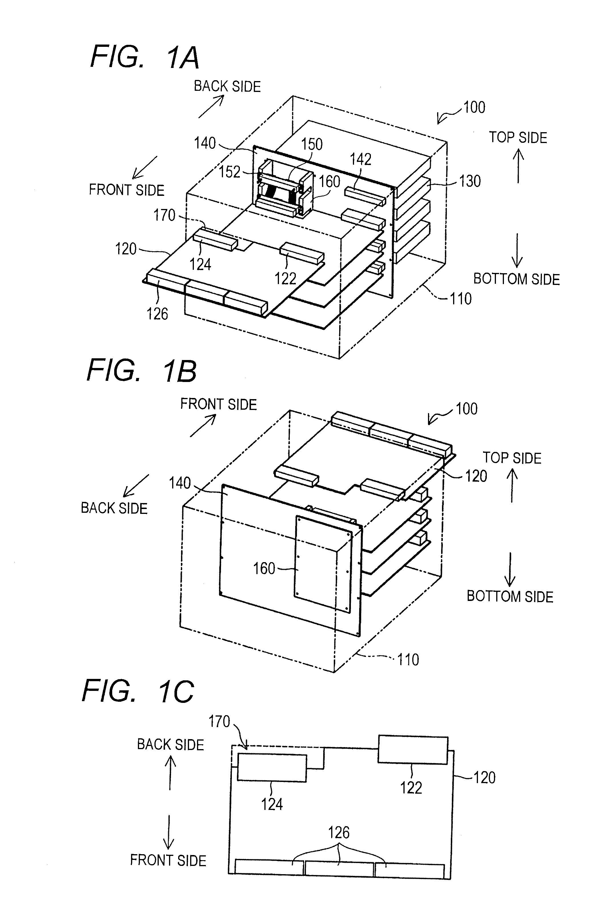
[0048]FIGS. 1A to 1C are schematic views showing the configuration of a switch 100, as an electronic device, according to a first embodiment. In FIGS. 1A to 1C, the switch 100 functions as a network communication device for transferring data (also more specifically called a frame or packet) in a computer network.
[0049]FIG. 1A is a front side perspective view of the switch 100. FIG. 1B is a back side perspective view of the switch 100. FIG. 1C is a top view of a circuit board unit 120. As shown in FIGS. 1A and 1B, the switch 100 includes plural circuit board units 120, plural power units 130, and a circuit board for interconnect 140, all of which are placed in a chassis 110. It is to be noted that FIGS. 1A and 1B also show the components of the switch 100, which are actually provided within the chassis 110 and invisible from the outside. FIG. 1B omits showing the power units 130. It is also possible that the switch 100 includes a cooling unit.
[0050]The circuit boar...
second embodiment
B. Second Embodiment
[0072]FIG. 4 is a schematic view showing the configuration of a switch 100a as an electronic device according to a second embodiment. The switch 100a of the second embodiment is different from the first embodiment shown in FIG. 1, in the configuration of a circuit board unit 120a. Other configurations of the switch 100a in the second embodiment are the same as in the first embodiment.
[0073]In the second embodiment, as shown in FIG. 4, the circuit board unit 120a of the switch 100a has a structure (a two-story structure) including a main circuit board 127 and a sub circuit board 128 mounted on the main circuit board 127. The main circuit board 127 and the sub circuit board 128 are both available for mounting a semiconductor device.
[0074]FIGS. 5A and 5B are schematic views showing the configuration of the circuit board unit 120a according to the second embodiment. FIG. 5A is a front side perspective view of the circuit board unit 120a. FIG. 5B is a top view of the ...
first modification
C1. First Modification
[0078]FIG. 6 is a schematic view showing the configuration of a switch 100b as an electronic device according to a first modification. In FIG. 6, the switch 100b of this modification is different from the first embodiment shown in FIG. 1 in the configuration of a circuit board unit 120b. In other words, in the switch 100b of this modification, a board unit side connector 122b is provided on the edge of the circuit board unit 120b on the front side but not the back side, to form a data transmission path through the cable 150. The circuit board units 120b are coupled to each other, through the board unit side connector 122b, through a cable side connector 152b, and through the cable 150.
[0079]Also in the switch 100b of this modification shown in FIG. 6, signals can be transmitted and received between the circuit board units 120b, by using both of the path through the circuit board for interconnect 140 and the path through the cable 150. This makes it possible to ...
PUM
 Abstract
Description
Claims
Application Information