Computer System

a computer system and computer technology, applied in computing, instruments, data conversion, etc., can solve the problems of inability to improve the overall throughput of the computer system, and the above-decoder cannot be provided on the memory bus, so as to improve the data transfer rate between the cpu and the peripheral device, and achieve the effect of improving the speed

Inactive Publication Date: 2007-11-01
YAMAHA CORP
View PDF2 Cites 2 Cited by
  • Summary
  • Abstract
  • Description
  • Claims
  • Application Information

AI Technical Summary

Benefits of technology

[0009] According to the present invention, such an advantage can be achieved that, even after the peripheral device is connected to the bus to which the memory has already been connected, the conflict between data read from the peripheral device and data read from the memory on the bus can be avoided. As a result, the peripheral device can be connected to the memory bus that is higher in speed than the external bus, and a data transfer rate between the CPU and the peripheral device can be improved.

Problems solved by technology

Therefore, a data transfer rate between the peripheral device and the CPU causes a bottleneck, and in some cases it is impossible to improve the throughput of the overall computer system.
The reason why such command transfer control should be executed is that, when the command is transferred to both the memory and the peripheral device, the data are read from both the memory and the peripheral device and a data conflict on the memory bus is caused.
However, such high-speed device does not exist at present and thus the above decoder cannot be provided on the memory bus.

Method used


Image

  • Computer System
  • Computer System
  • Computer System

Examples


Embodiment Construction

[0027] A best mode for carrying out the present invention will be explained with reference to the drawings hereinafter.

[Configuration]

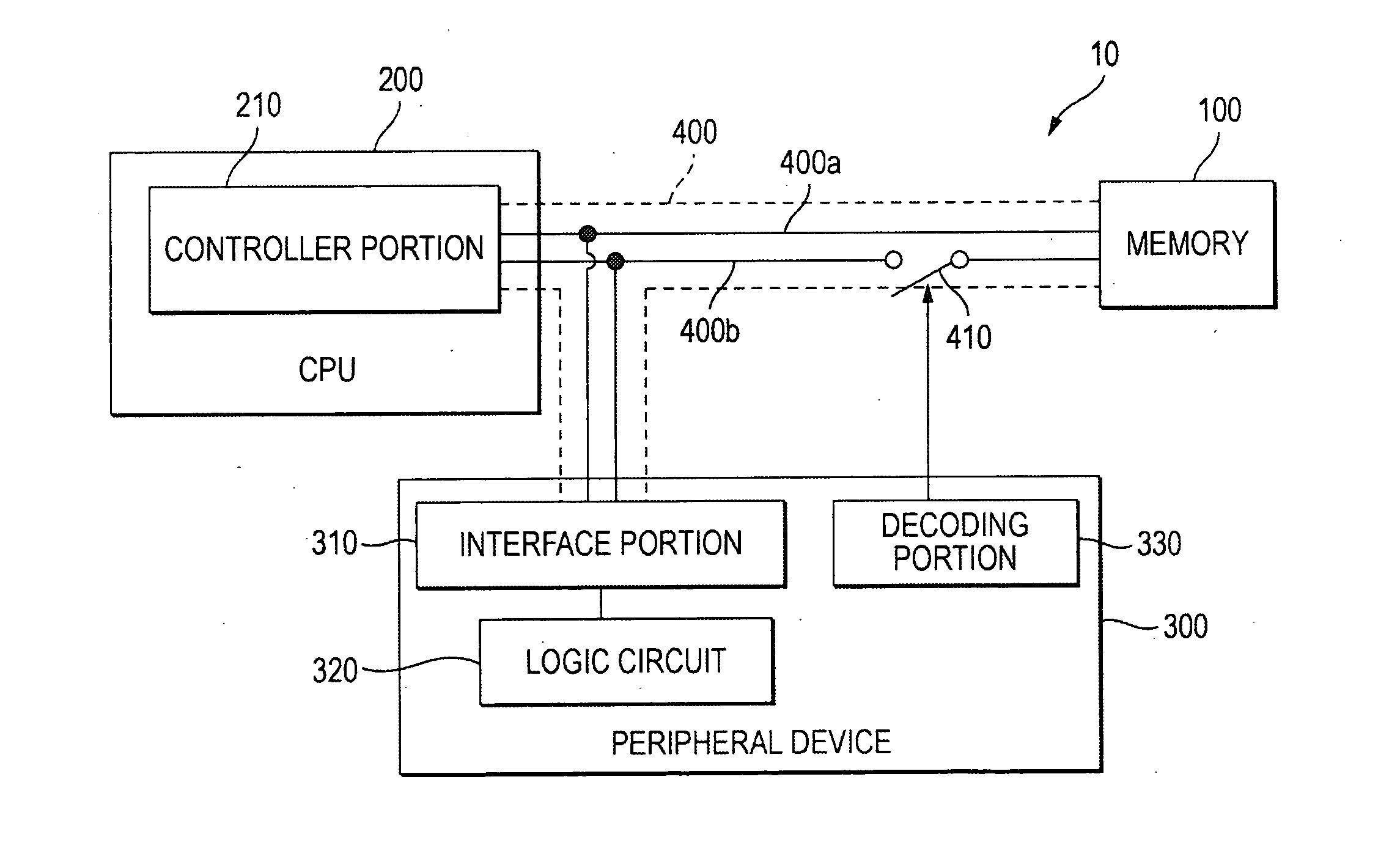
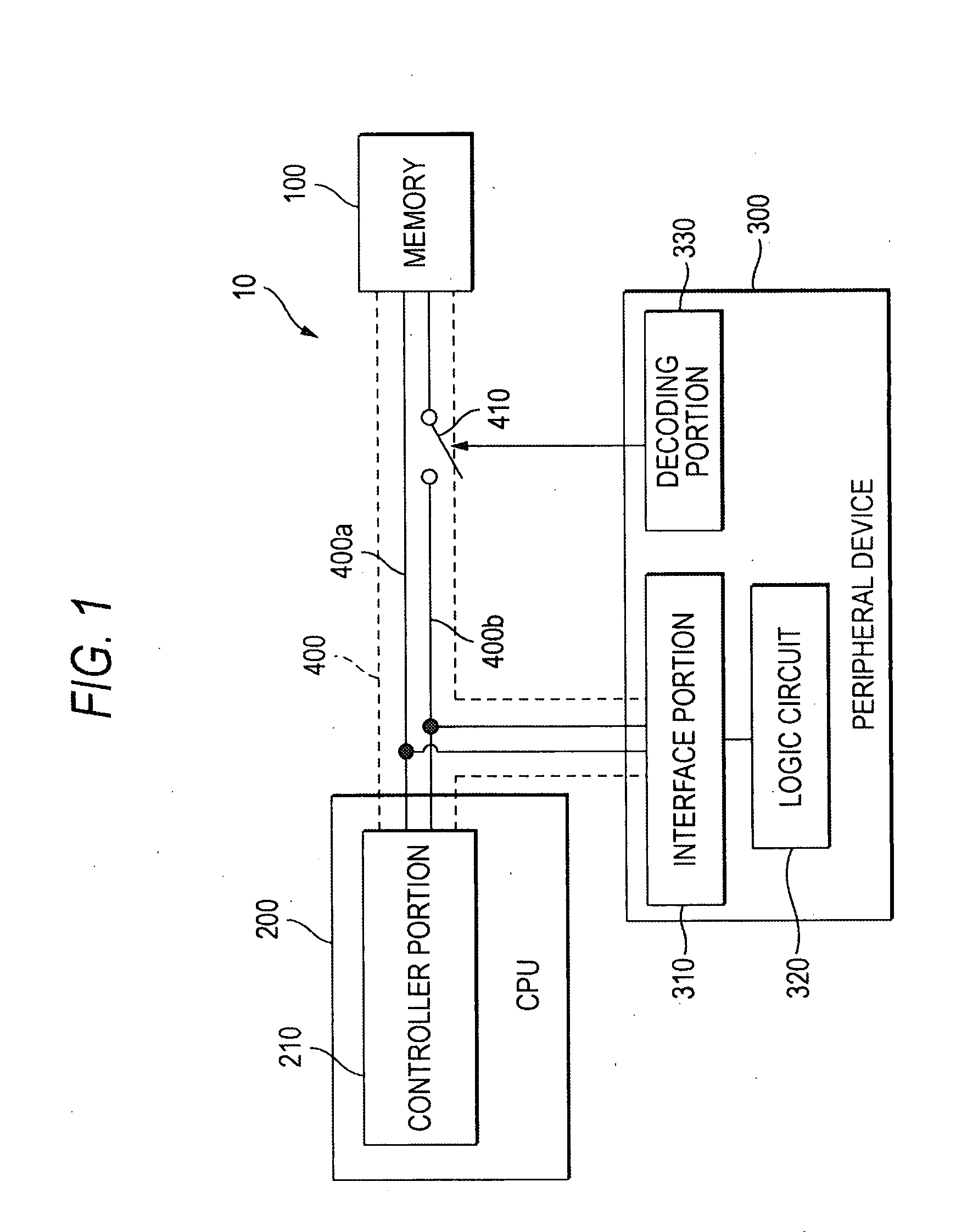
[0028]FIG. 1 is a block diagram showing a configurative example of a computer system 10 according to an embodiment of the present invention. As shown in FIG. 1, this computer system 10 includes a memory 100, a CPU 200, a peripheral device 300, and a bus 400 for transferring data and commands between these constituent elements.

[0029] The bus 400 is a memory bus that is operated in synchronism with a system clock, for example. As shown in FIG. 1, the bus 400 contains a command bus 400a and a data bus 400b. Here, the command bus 400a is a bus that is used to transfer an address indicating an access object and a command representing access contents between the memory 100 or the peripheral device 300 and the CPU 200. Also, the data bus 400b is a bus that is used to transfer the processed result of the command or the data as the processed object of the c...


PUM


Abstract

In a computer system that includes a memory, a peripheral device to which an address overlapping with a part of an address space assigned to the memory is assigned, a CPU for sending a signal responding an address of an access destination to a bus when the CPU accesses either the memory or the peripheral device, and a bus for connecting the CPU and the peripheral device, a switch for switching a connection and a disconnection between the CPU and the memory via the bus, and an interface portion for receiving a signal sent to the bus from the CPU and specifying an address indicated by the signal and a decoding portion for turning OFF the switch when the address specified by the interface portion is the address assigned to its own device is provided to the peripheral device.

Description

TECHNICAL FIELD [0001] The present invention relates to the technology to control the data transfer between a memory and a peripheral device connected to a CPU via a bus and the CPU. BACKGROUND ART [0002] In order to improve throughput of a computer system containing CPU (Central Processing Unit), memory, and the like, for example, improvements in a high integration and a high speed of a semiconductor memory device constituting the memory, particularly DRAM (Dynamic Random Access Memory) are proceeding. As an example of the improvements, such an instance can be offered that a memory should be composed of SDRAM (Synchronous DRAM) that operates in synchronism with a clock supplied from a clock generator to CPU (referred to as a “system clock” hereinafter). Also, various technologies regarding improvements in a structure of SDRAM and its utilizing method have been proposed, and the technology disclosed in Patent Literature 1 can be cited as an example. In this Patent Literature 1, the ...

Claims


Application Information

Patent Timeline
Patent Type & Authority Applications(United States)
IPC IPC(8): G06F3/00
CPCG06F13/4234G06F13/1668
Inventor OKAMOTO, KAZUKISUZUKI, TOMOHIRO
Owner YAMAHA CORP
Why Eureka
Try Eureka