
Connectors and assemblies having a plurality of moveable mating arrays

Inactive Publication Date: 2011-07-14
TE CONNECTIVITY CORP
View PDF2 Cites 1 Cited by
  • Summary
  • Abstract
  • Description
  • Claims
  • Application Information

AI Technical Summary

Benefits of technology

[0005]Accordingly, there is a need for a connector that facilitates interconnection of a printed circuit (e.g., circuit board) to another component when the printed circuit and the component are oriented in an orthogonal relationship. Furthermore, there is also a need for altern

Problems solved by technology

However, when the header / receptacle assembly is on a surface of the daughter card and faces a direction perpendicular to the insertion direction (e.g., perpendicular to a surface of the daughter card) and the connector is on the backplane circuit board and also faces a direction perpendicular to the insertion direction, it may be difficult to properly align and mate the header / receptacle assembly and the connector.

Method used


Image

  • Connectors and assemblies having a plurality of moveable mating arrays
  • Connectors and assemblies having a plurality of moveable mating arrays
  • Connectors and assemblies having a plurality of moveable mating arrays

Examples


Embodiment Construction

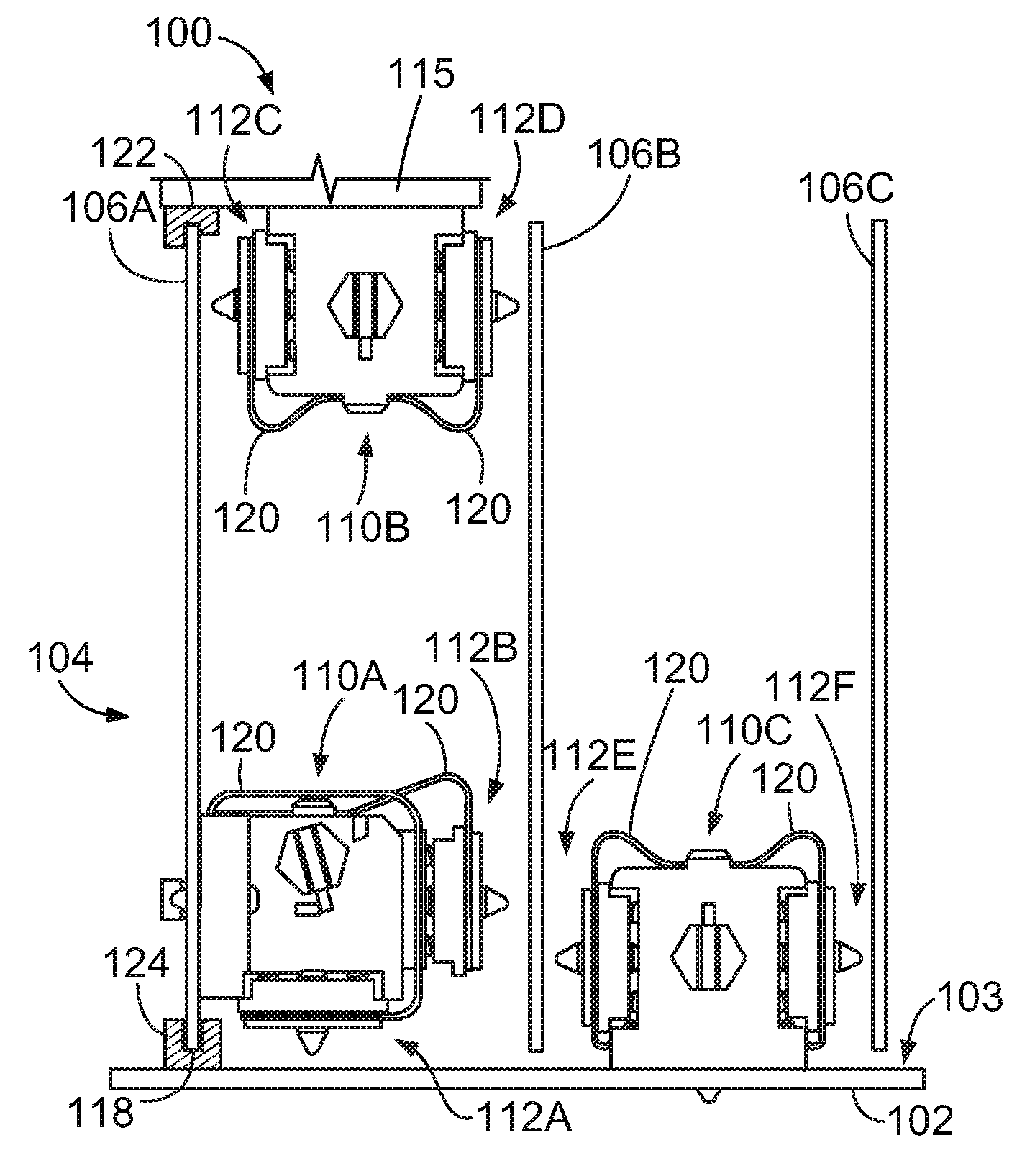
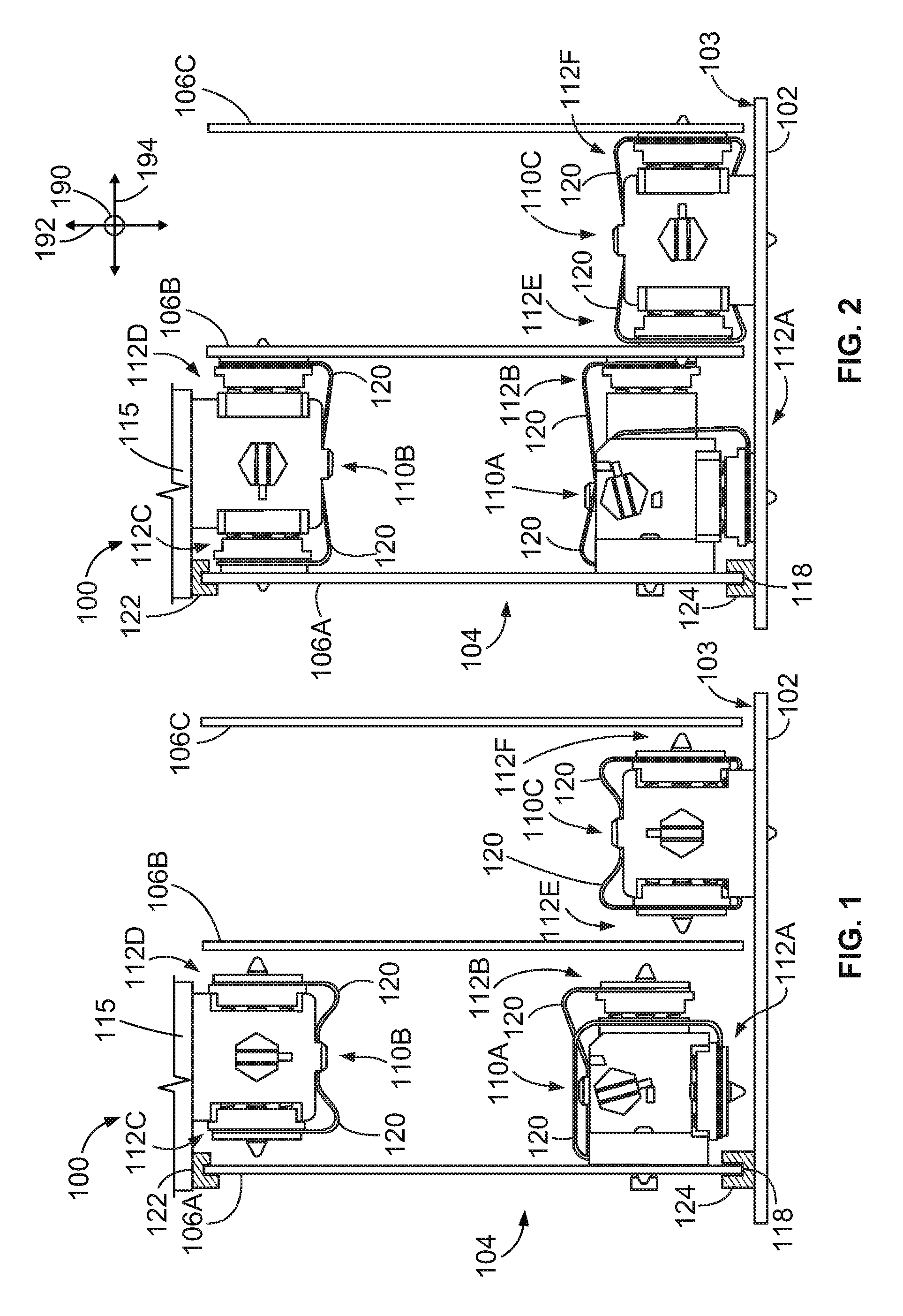
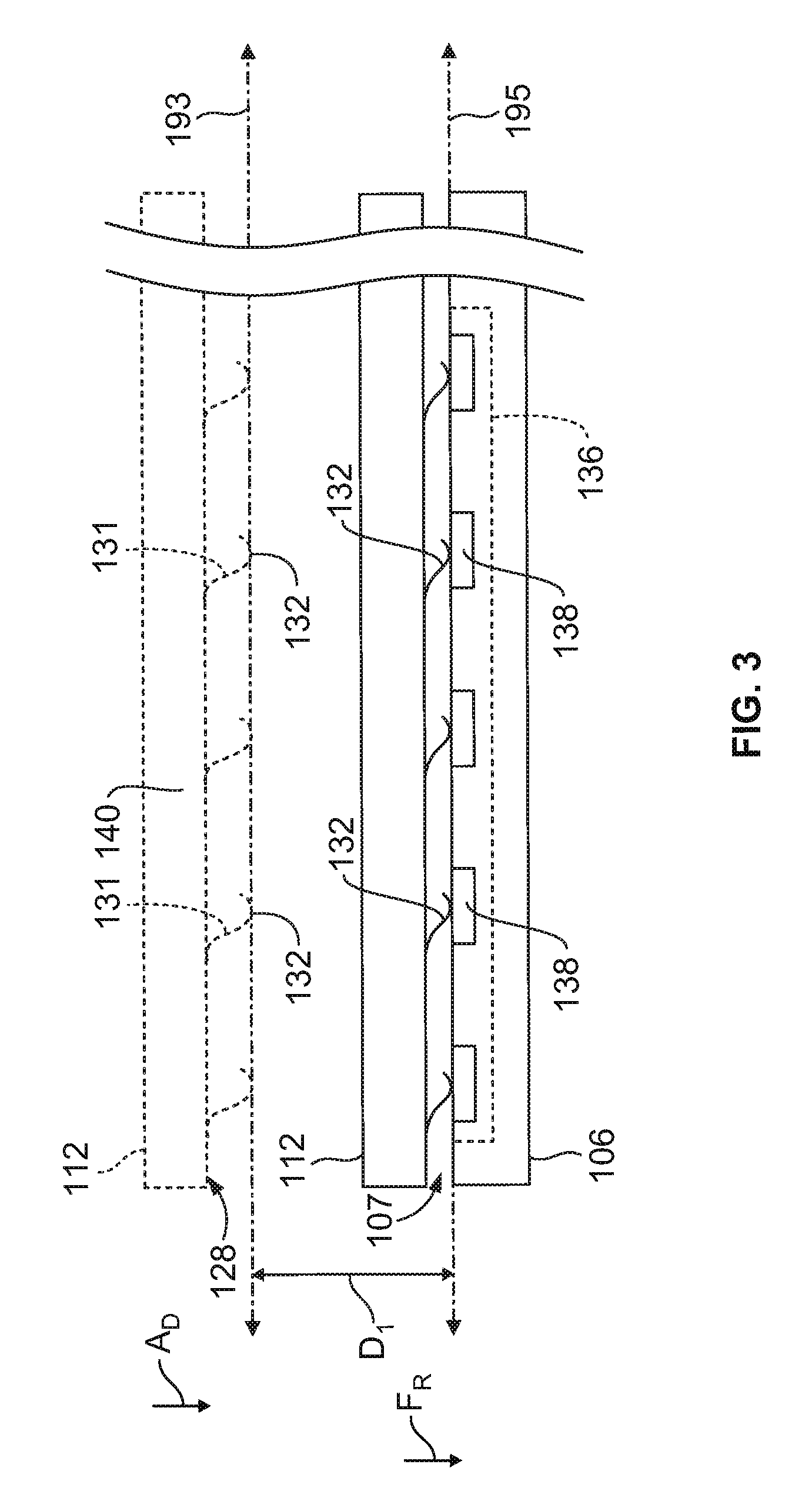
[0024]Embodiments described herein include connectors that are configured to establish at least one of an electrical and optical coupling (e.g., for transmitting data signals or power) between different components. The components that are interconnected by the connectors may be printed circuits (e.g., circuit boards or flex circuits), other connectors (e.g., optical and / or electrical connectors), or any other components that are capable of establishing an electrical or optical coupling to the connectors. The connectors include one or more moveable mating arrays that have terminals that are configured to couple to or engage with other terminals to establish the electrical and / or optical coupling. For example, the terminals may be mating contacts for establishing an electrical connection or optical fiber terminals for establishing an optical connection. Embodiments described herein also include coupling mechanisms that are configured to move the mating arrays from a retracted position...


PUM


Abstract

A connector configured to communicatively couple different components. The connector includes a base frame that extends along a longitudinal axis between a pair of frame ends and moveable first and second mating arrays comprising respective mating surfaces having terminals arranged thereon. The connector also includes a coupling mechanism supported by the base frame. The coupling mechanism holds the first and second mating arrays and moves the first and second mating arrays between retracted and engaged positions. The first and second mating arrays are spaced apart from a select component when in the corresponding retracted position. The first and second mating arrays are communicatively coupled to the select component when in the corresponding engaged position. The coupling mechanism initiates movement of the first mating array from the retracted position toward the engaged position while the second mating array remains stationary with respect to the base frame.

Description

CROSS-REFERENCES TO RELATED APPLICATIONS[0001]Subject matter described herein is similar to subject matter described in U.S. patent application Ser. No. 12 / 428,851, entitled “REMOVABLE CARD CONNECTOR ASSEMBLIES HAVING FLEXIBLE CIRCUITS,” and U.S. patent application Ser. No. 12 / 428,806, entitled “CONNECTOR ASSEMBLIES AND SYSTEMS INCLUDING FLEXIBLE CIRCUITS,” both of which were filed on Apr. 23, 2009, and similar to subject matter described in a patent application having Attorney Docket No. CC-00938 (958-2368US), entitled “CONNECTORS AND ASSEMBLIES HAVING A PLURALITY OF MOVEABLE MATING ARRAYS,” filed contemporaneously herewith, all of which are incorporated by reference in the entirety.BACKGROUND OF THE INVENTION[0002]The subject matter herein relates generally to connectors, and more particularly, to connectors that are configured to communicatively couple different components.[0003]Some systems, such as servers, routers, and data storage systems, utilize connector assemblies for tra...

Claims


Application Information

Patent Timeline
IPC IPC(8): G02B6/36H01R13/62
CPCG02B6/389G02B6/3897H05K7/1439H01R12/714H01R12/88H01R12/7082
Inventor MULFINGER, ROBERT NEILHAMNER, RICHARD ELOFREISINGER, JASON M'CHEYNE
Owner TE CONNECTIVITY CORP
Learn More