Pump enclosure

Active Publication Date: 2010-12-14
EDWARDS LTD
View PDF28 Cites 3 Cited by
  • Summary
  • Abstract
  • Description
  • Claims
  • Application Information

AI Technical Summary

Benefits of technology

[0009]Control circuitry typically comprises one or more printed circuit board assemblies, and so advantageously at least one of the extrusions is profiled to receive a printed circuit board assembly. This can facilitate location of the assembly on the extrusion before the extrusions have been connected together. The outer extrusion conveniently has a

Problems solved by technology

This serves to maximise the spacing of the temperature-sensitive circuitry from the pump, which, during use, can typically generate temperatures of up to 150° C. However, mounting such enclosures externally on to the pump enclosure increases b

Method used


Image

  • Pump enclosure
  • Pump enclosure
  • Pump enclosure

Examples


Embodiment Construction

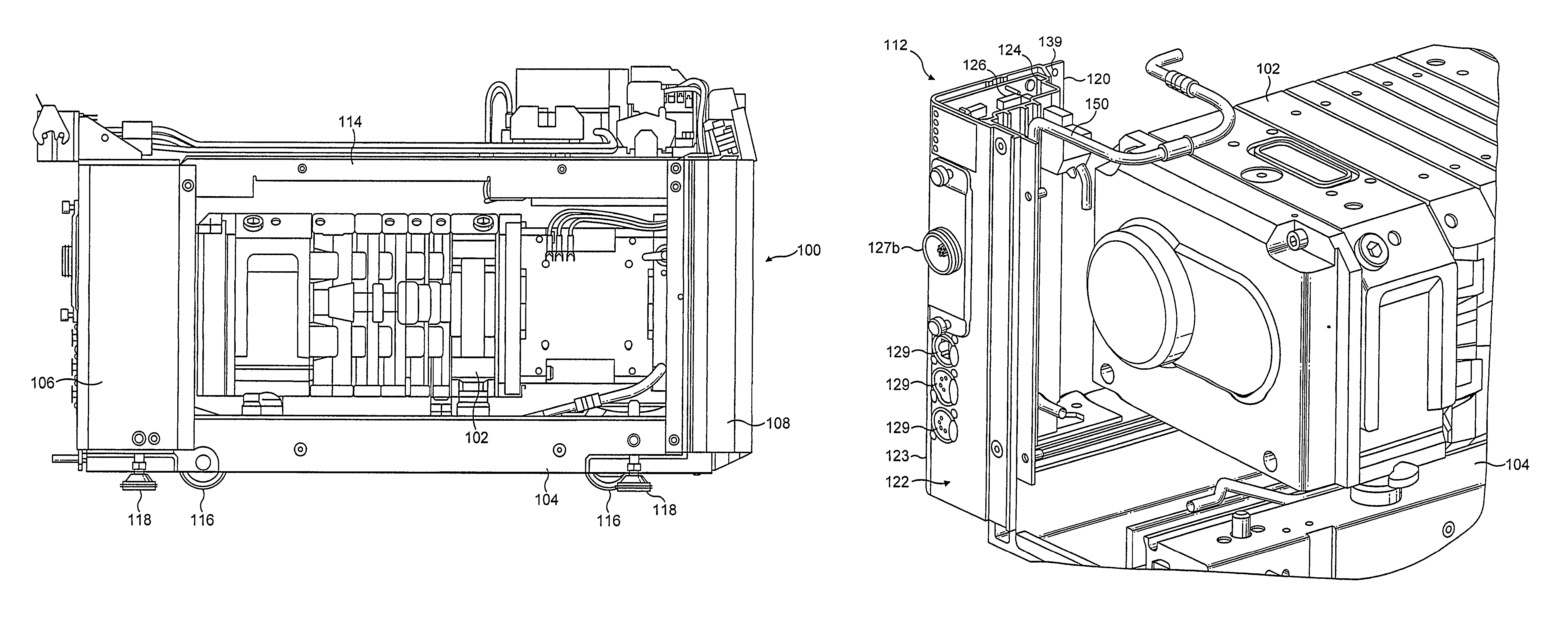
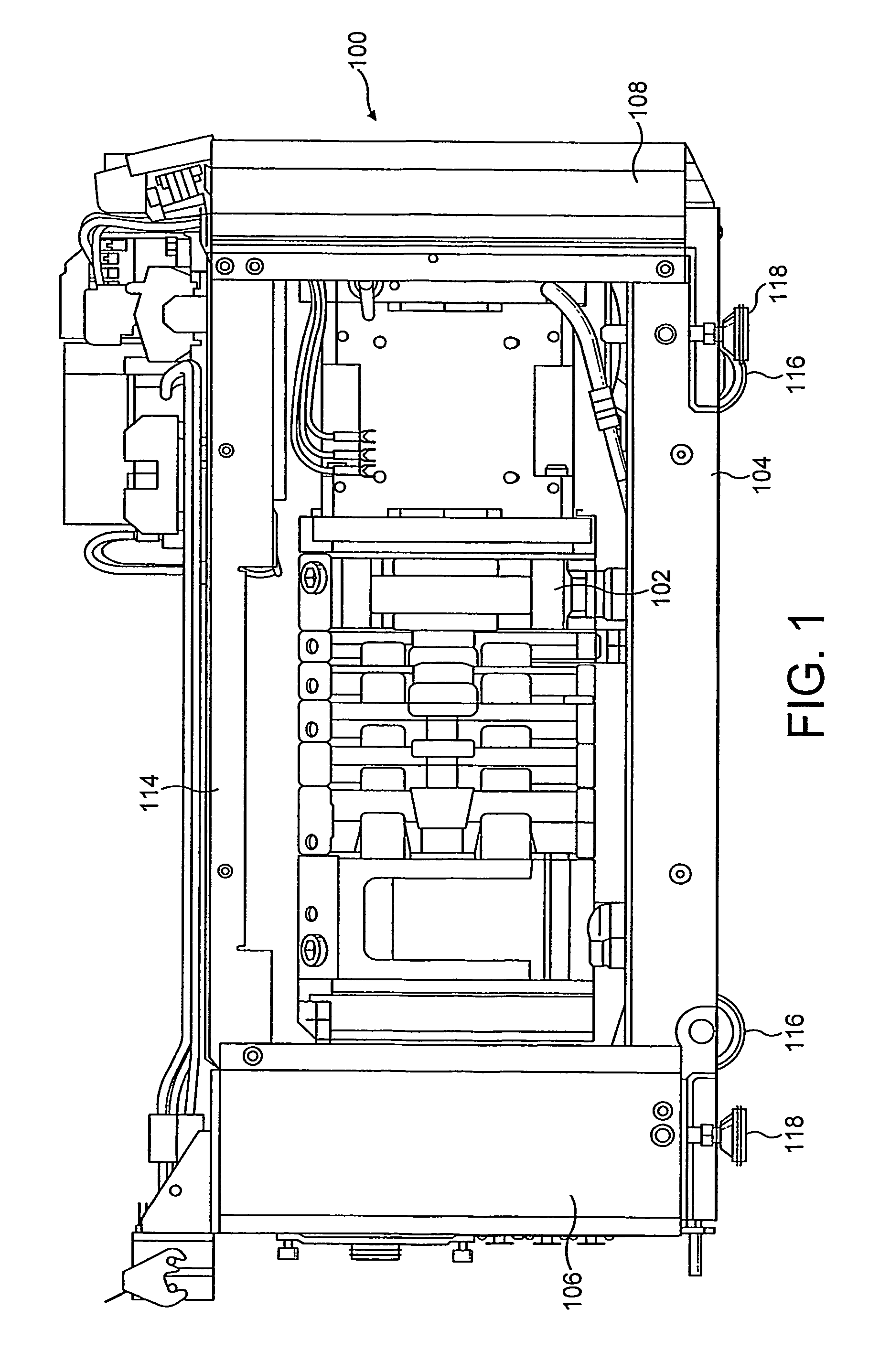
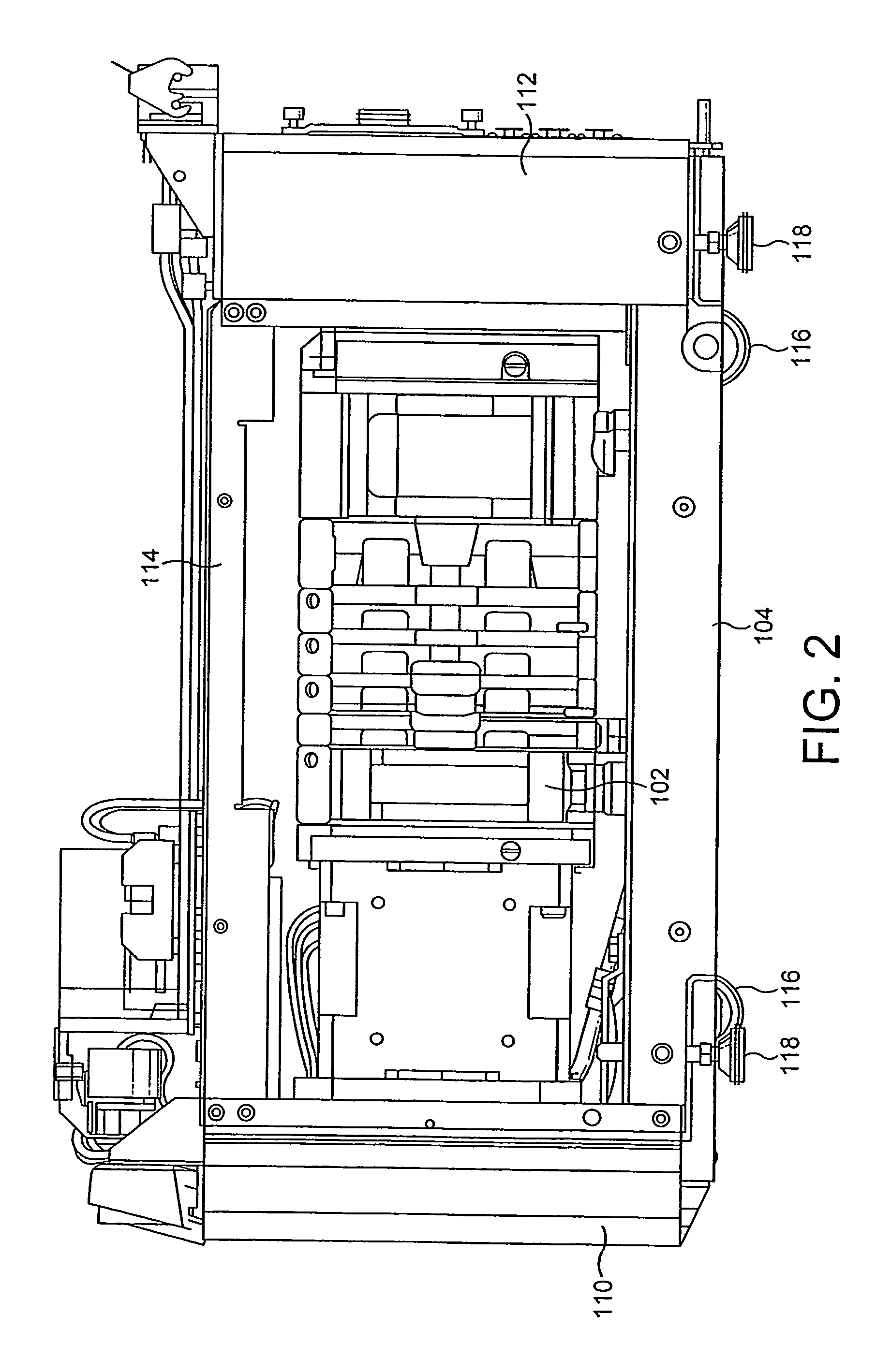
[0024]With reference first to FIGS. 1 to 3, a pump enclosure 100 for a pump 102 comprises a chassis, or base, 104, four pillars 106, 108, 110, 112 each located at a respective corner of the base 104, and a cover 114.

[0025]The base 104 comprises an extruded member, or extrusion, having slots formed therein for receiving, inter alia, wheels 116 and feet 118 for the enclosure, and power leads and other electrical cables (not shown) for the pump 102. The base 104 may comprise a single extrusion, or a plurality of extrusions bonded together. The base 104 is preferably formed from aluminium, which is a relatively cheap, lightweight, corrosion resistant material having sufficient mechanical strength to enable the base 104 to support the pump 102 and the remainder of the enclosure 100. Corner pillars 106, 108, 110 and 112 are also preferably formed from aluminium extrusions (the structure of corner pillar 112 is described in more detail below). Cover 114 may be formed from steel or any othe...


PUM


Abstract

A pump enclosure includes a base, a plurality of pillars, and a cover. One of the pillars includes interconnecting aluminium extrusions defining therebetween a housing for pump control circuitry. This pillar can also provide a heat sink for dissipating heat generated during use of a pump away from the control circuitry.

Description

FIELD OF THE INVENTION[0001]This invention relates to a pump enclosure.BACKGROUND OF THE INVENTION[0002]Traditionally, control circuitry for a pump is located in dedicated enclosures mounted on the external walls of the pump enclosure. This serves to maximise the spacing of the temperature-sensitive circuitry from the pump, which, during use, can typically generate temperatures of up to 150° C. However, mounting such enclosures externally on to the pump enclosure increases both the weight and the foot-print of the pump enclosure. Whilst these enclosures may be mounted on to the internal walls of the pump enclosure to reduce the foot-print, cooling fans would be required to prevent over-heating of the control circuitry during use of the pump. The use of such fans would increase power consumption and costs, and the air disturbance caused by the fans could be detrimental to, for example, a clean room in which the pump being used.[0003]It is an aim of the present invention to minimise t...

Claims


Application Information

Patent Timeline
IPC IPC(8): A47B77/08F04B39/00F04B53/08F04D29/60
CPCF04B39/0033F04D29/605F04B53/08
Inventor SAUNDERS, ROBERT JOHN
Owner EDWARDS LTD
Why Eureka
Try Eureka