Removable trigger guard

Inactive Publication Date: 2011-07-21
SMITH & WESSON
View PDF11 Cites 17 Cited by
  • Summary
  • Abstract
  • Description
  • Claims
  • Application Information

AI Technical Summary

Benefits of technology

[0009]Accordingly, the present invention provides a removable trigger guard that prevents debris from comi

Problems solved by technology

In some usage situations, such as combat conditions in desert regions, sand and other field debris can find its way into the lower receiver and become lodged in and under the trigger mechanism.
As a result, the trigger mechanism may require cleaning.
Similarly, known trigger guards are not involved with preventing or addressing the problem of debris interrupt

Method used


Image

  • Removable trigger guard
  • Removable trigger guard
  • Removable trigger guard

Examples


Embodiment Construction

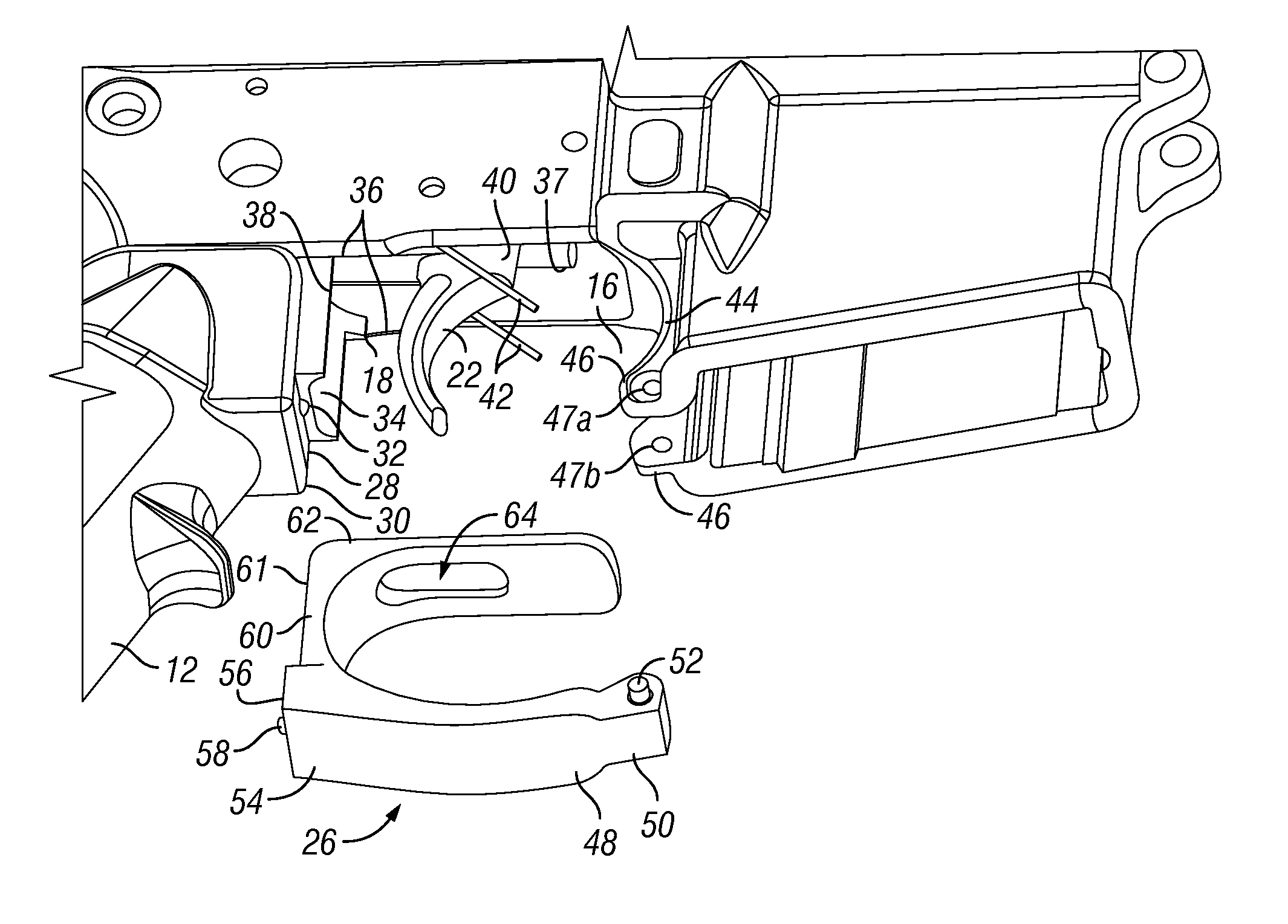
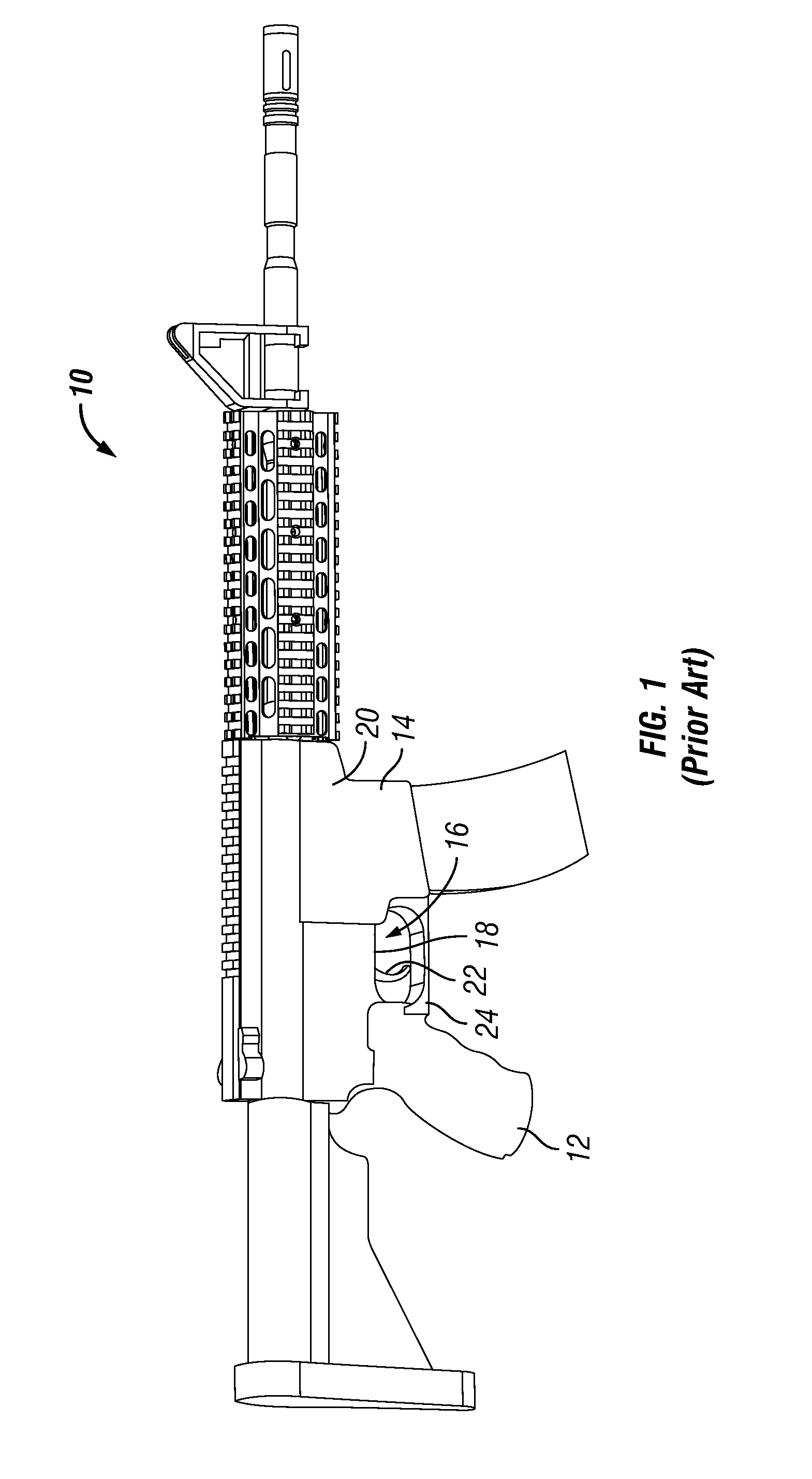
[0032]Referring to FIG. 1, a firearm 10 according to the prior art, such as a M-16 style firearm, is shown. The firearm 10 has a grip 12 and a magazine well 14 that, together, define a trigger space 16 disposed adjacent to a partly-opened lower surface 18 of a receiver 20 of the firearm 10. The grip 12 commonly is mounted to the receiver 20, while the magazine well 14 may be formed integral with or as a part of the receiver 20. The receiver 20 houses a trigger mechanism (not shown in FIG. 1) that is operable by a trigger 22, which protrudes through the lower surface 18 of the receiver 20 into the trigger space 16. The firearm 10 also has a trigger guard 24 disposed between the grip 12 and the magazine well 14 to define and enclose the trigger space 16. The trigger guard 24 prevents actuation of the trigger 22 by inadvertent insertion of an object or finger into the trigger space 16.

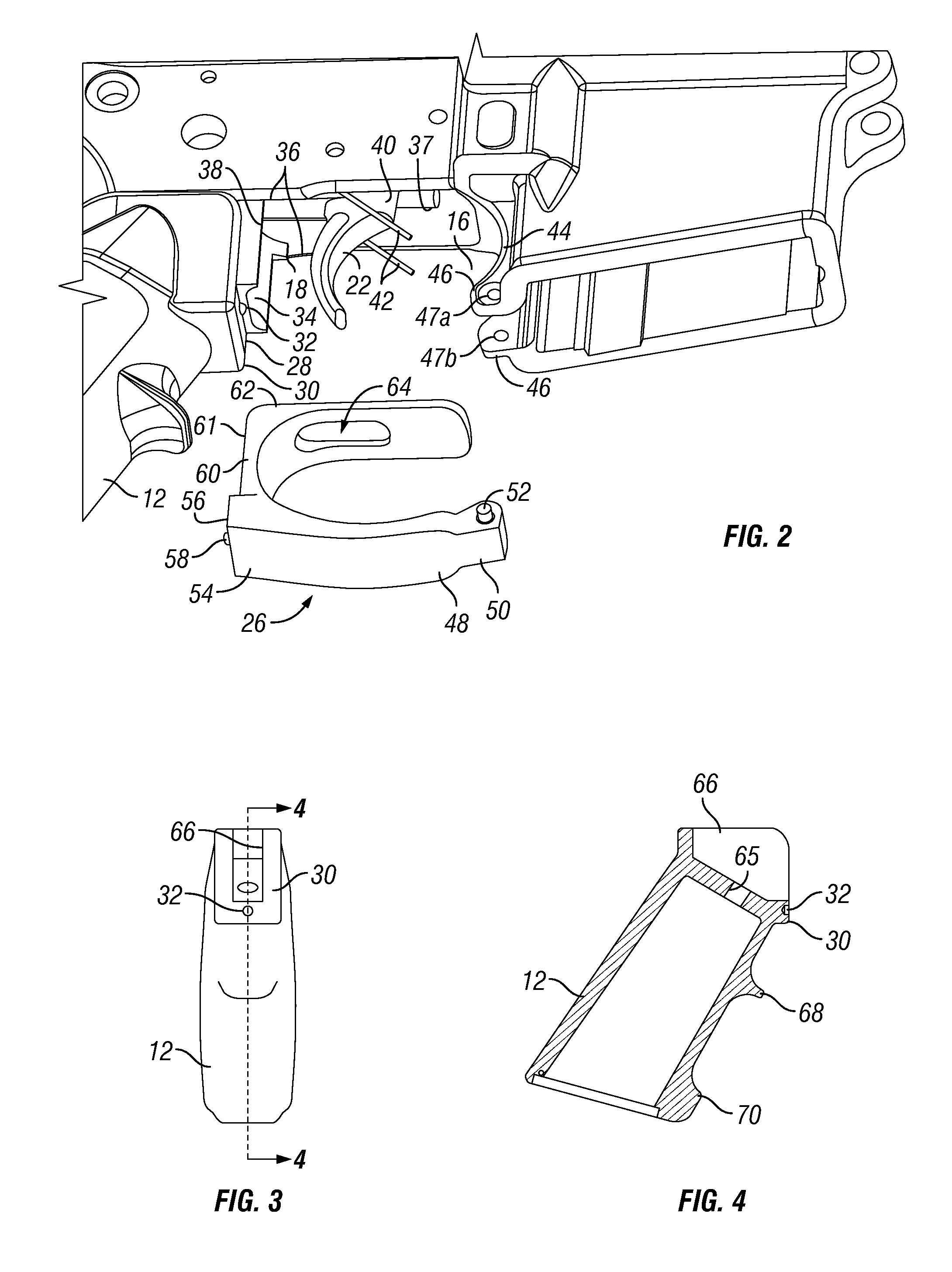
[0033]Referring to FIG. 2, the trigger space 16 is shown with a removable trigger guard 26, according ...


PUM


Abstract

A removable trigger guard for a rifle. The removable trigger guard includes a first arm that is disposed between a magazine and a grip of the firearm, a body portion disposed along an upper portion of the grip, and a second arm portion that is disposed along a lower surface of the rifle and between the grip and the magazine. The first arm includes a ball bearing and a detent pin that engage a yoke of the magazine. The body portion includes another ball bearing that snap fits into engagement with a yoke formed in the magazine. The second arm includes an opening that receives a trigger that protrudes from the lower surface. The removable trigger guard can be installed by hand without tools and can be removed with the use of the tip of an ammunition cartridge.

Description

CROSS REFERENCE TO RELATED APPLICATION[0001]The present utility application claims priority to U.S. Provisional Application Ser. No. 61 / 295,328, filed Jan. 15, 2010, hereby incorporated herein by reference in its entirety.FIELD OF THE INVENTION[0002]The invention relates to a trigger guard for a firearm. In particular, the present invention relates to a removable trigger guard for an M-16 style rifle.BACKGROUND OF THE INVENTION[0003]Trigger guards mounted on rifles are known to protect the trigger from inadvertent actuation that can, under some circumstances, result in the discharging of a round of ammunition. Such trigger guards are, in general, designed to avoid interfering with or otherwise impacting the normal operation of the trigger.[0004]In some usage situations, such as combat conditions in desert regions, sand and other field debris can find its way into the lower receiver and become lodged in and under the trigger mechanism. As a result, the trigger mechanism may require c...

Claims


Application Information

Patent Timeline
IPC IPC(8): F41A19/00F41A35/02F41A29/00
CPCF41A19/11
Inventor FINDLAY, DAVID
Owner SMITH & WESSON
Why Eureka
Try Eureka