However, the
universal joint needles are subjected to unusually high pressures which are transferred to the bearing cup surfaces at the area of their contact.
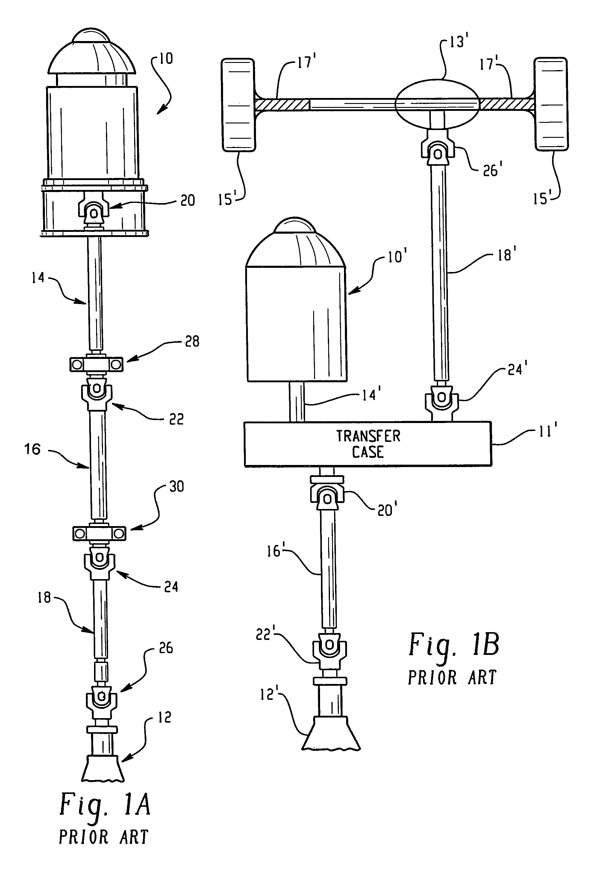
There are several drawbacks associated with the use of needles in bearing assemblies, particularly bearing assemblies used in
drive shaft arrangements.
One drawback is that, unless periodically lubricated, the bearing assembly will wear and deteriorate so significantly that the bearing member and / or the member (such as a
trunnion) having the load transfer surface will require replacement.
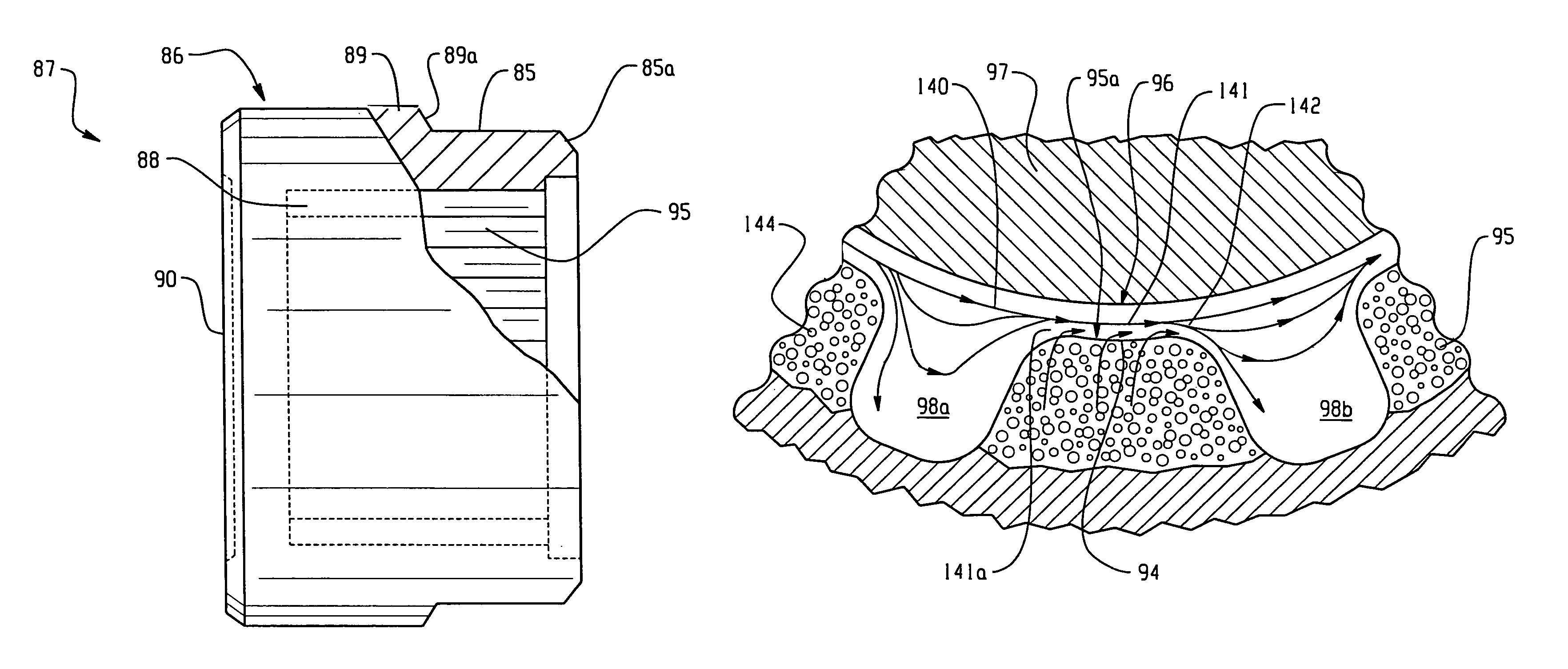
Such wear is caused by the normal rolling action between the bearing and the load transfer surface.
The relative movement or rolling action causes friction and heat which dries out the
lubricant thereby causing the generation of deleterious debris (wear particles), typically 25-50 microns in
diameter.
As wear continues, the quantity and size of the debris increases.
The continuously increasing quantity and size of debris can lodge at the needles causing them to slide rather than roll.
This results in the creation of grooves called brinnels, which further
restrict the rolling and increase friction, generating more and larger debris.
Frequent
lubrication and periodic bearing replacement add an undesirable maintenance cost to the needle using bearing assembly that is necessary to ensure acceptable performance.
Another drawback is that when the bearing assembly with needles is subjected to sudden impacts, the needles transmit extremely
high pressure shocks to the bearing and the member having the load transfer surfaces.
The needles, due to their small contact area (essentially a line), amplify the pressure transmitted which frequently results in a breakdown of the bearing surfaces causing generation of deleterious debris commonly referred to as “galls”.
However, they, like the debris causing brinneling, increase in quantity and grow larger over time.
Should the wear particles exceed about 150 microns in size, bearing failure in the form of surface seizure, is likely to be imminent.
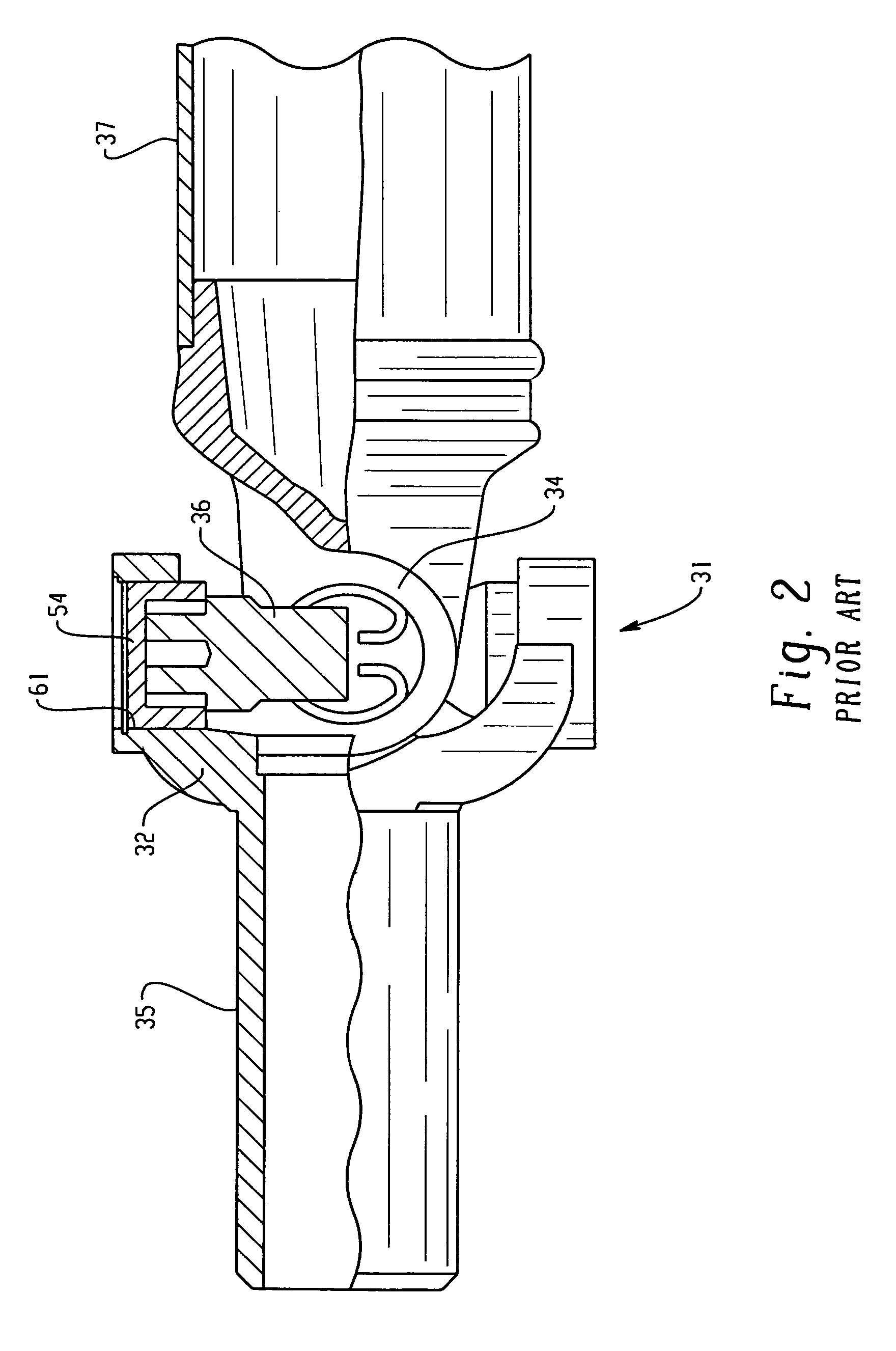
Yet another drawback related to the use of needles in bearing assemblies is the cost factor in manufacturing the needles as additional components of the bearing assemblies and the cost of assembling the needles in a bearing assembly.
For example, in the manufacture of universal joints, bearing assemblies having needles are more expensive due to the manufacturing cost of the needles, the cost of assembling the needles in the
trunnion and bearing sets of the
universal joint and the cost of the required assembly equipment.
Still another drawback of using needles in bearing assemblies is related to the means for enabling periodic
lubrication of the bearing assembly.
In either arrangement, the manufacturing costs of the bearing assembly is undesirably increased when such means for enabling periodic lubrication can be incorporated in the bearing assembly.
Direct contact leads to friction causing excessive heat and wear, as well as eventual seizure.
There is no mechanism for removing
wear debris after it is generated in these types of bearings.
Moreover,
power transmission bearings, including
universal joint bearings, are oscillatory at constantly varying speeds which would not permit a film to be generated.
Thus, these types of bearings are typically unsuitable for use in
power transmission bearing assemblies.
Generally, prior art bearings were not designed for removing debris between bearing surfaces and the load transfer surface.

