Lower Structure of Vehicle Body Rear Portion

Inactive Publication Date: 2011-07-21
SUZUKI MOTOR CO LTD
View PDF2 Cites 27 Cited by
  • Summary
  • Abstract
  • Description
  • Claims
  • Application Information

AI Technical Summary

Benefits of technology

[0015]Accordingly, the rigidity of the vehicle body is higher in the front part of each of the rear side members on the front side of the spare tire cross member, and is lower in the rear part thereof on the rear side of the spare tire cross member. Therefore, when the load is applied to the vehicle body rear portion from behind the vehicle, the chevron foldings of the rear side members can be formed reliably. The chevron folding has a shape in which the joint part joining with the spare tire cross member protrude upward. In the same manner, the chevron folding on the rear floor panel can also be formed reliably. Therefore, the rear part having the lower rigidity is deformed in the front and rear direction of the vehicle, and thereby the load is absorbed. This reduces the degree of upward protruding of the chevron foldings of the rear side members and the rear floor panel. Thereby, components arranged below the rear floor panel can still be spaced away from each other. Therefore, it is possible to efficiently absorb the load to be applied thereto from behind the vehicle while preventing the components from coming close to each other and coming into contact with each other.
[0016]Regarding the lower structure of a vehicle body rear portion according to the embodiment of the present invention, the rear part of each of the rear side members is formed to have a plate thickness smaller than the plate thickness of the front part of each of the rear side members, and the front part and the rear part of each of the rear side members are connected together by tailored blank welding. This reliably makes the rigidity of the rear part lower than that of the front part, therefore providing the aforementioned effects. Furthermore, this eliminates the need for adding reinforcing parts for enhancing the rigidity of the front part and therefore eliminates the need for considering space for arranging the reinforcing parts. Accordingly, the layout of the components is not limited, and therefore the design flexibility is not reduced. In addition, there is no increase in vehicle weight by the

Problems solved by technology

Furthermore, this causes a problem.
This leads to limitations on both the layout of space below the rear floor panel in which many components are required to be arranged, as well as the shape

Method used


Image

  • Lower Structure of Vehicle Body Rear Portion
  • Lower Structure of Vehicle Body Rear Portion
  • Lower Structure of Vehicle Body Rear Portion

Examples


Example

DETAILED DESCRIPTION OF THE DRAWINGS

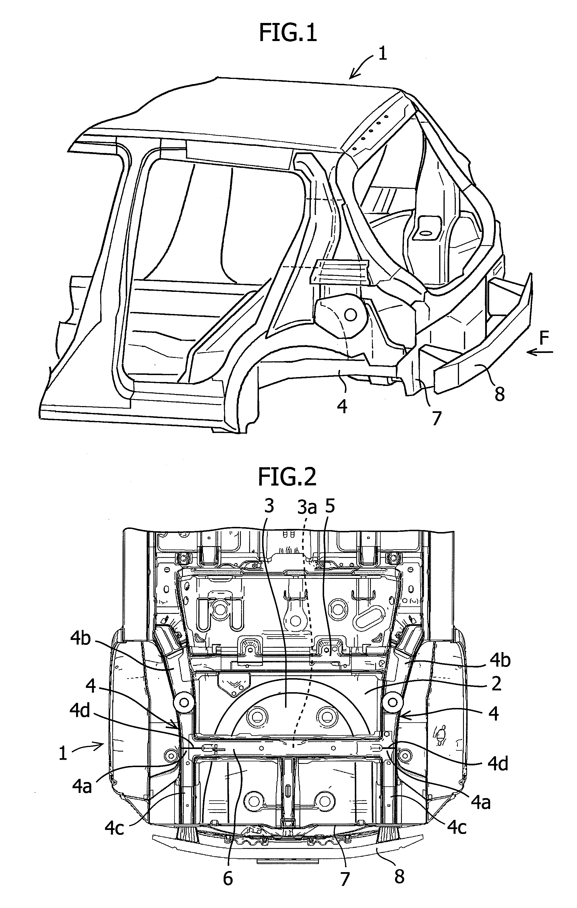
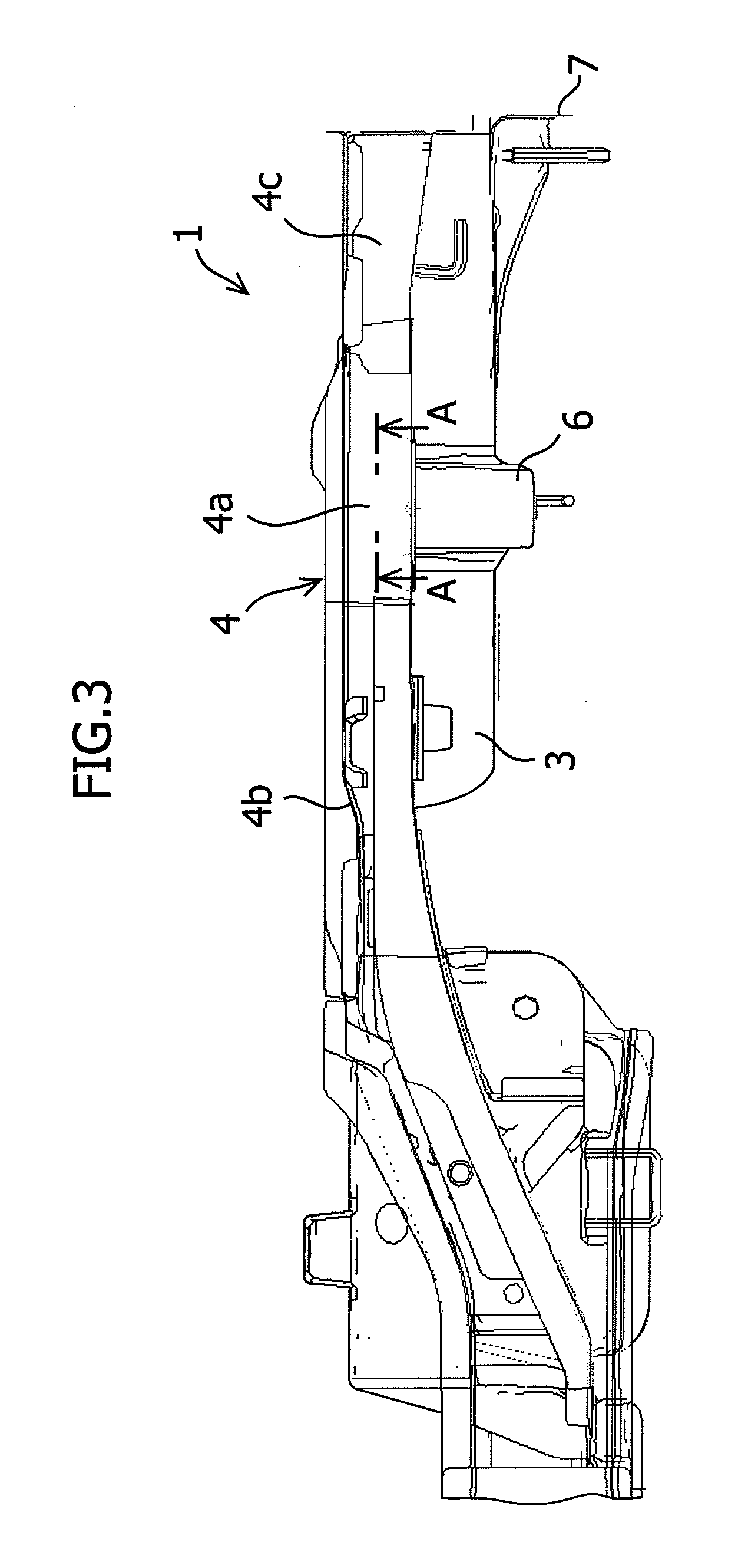
[0026]Hereinbelow, the structure of a vehicle body rear portion 1 of a vehicle according to an embodiment of the present invention will be described with reference to FIGS. 1 to 6.

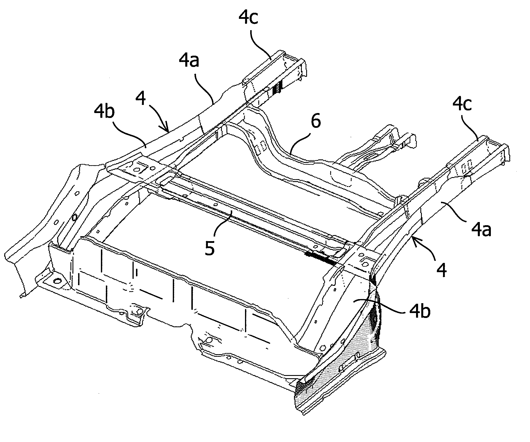
[0027]A description is given of a main structure of the vehicle body rear portion 1 with reference to FIGS. 1 to 4. The vehicle body rear portion 1 located on the vehicle rear side is provided with a rear floor panel 2. The rear floor panel 2 spreads in a horizontal direction to form a floor of a cabin. A spare tire housing 3 for accommodating a spare tire (not shown) is formed on the rear floor panel 2 in such a manner as to be recessed downward. Rear side members 4 extending in a front and rear direction of the vehicle are respectively provided on right and left ends of the rear floor panel 2, in a width direction of the vehicle. Cross sections of the rear side members 4 in the width direction of the vehicle are substantially shaped like a hat which has an opening in i...


PUM


Abstract

A lower structure of a vehicle body rear portion includes: a rear floor panel in a rear portion of a vehicle; a spare tire housing formed on the floor panel in such a manner as to be recessed downward; rear side members extending in a front and rear direction on respective right and left ends of the floor panel; a rear cross member arranged in front of the housing and connecting the paired right and left side members; and a spare tire cross member attached to the housing and connecting the paired side members, wherein a rear part of each of the side members is formed to have a rigidity lower than a rigidity of a front part thereof, the rear part extending on the rear side from a joint part joining with the spare tire cross member, the front part extending on the front side from the joint part.

Description

FIELD OF THE INVENTION[0001]The present invention relates to a lower structure of a vehicle body rear portion, which is formed so as to be capable of absorbing a load applied from behind the vehicle.BACKGROUND OF THE INVENTION[0002]In a recent vehicle, when a load is applied from behind the vehicle, a vehicle body rear portion is required to absorb the load. Therefore, a lower structure of the vehicle body rear portion is configured in many cases in such a manner as to be able to absorb a load applied from behind the vehicle by deforming constituent members (such as a rear floor panel, rear side members extending in a front and rear direction of the vehicle on the respective ends of the rear floor panel, and the like) of the lower structure.[0003]For example, Japanese Unexamined Patent Publication No. 2006-205810 and Japanese Unexamined Patent Publication No. 2007-131259 each disclose the following structure. In the structure, rear side members are formed such that a load applied fr...

Claims


Application Information

Patent Timeline
IPC IPC(8): B62D25/08
CPCB62D25/2027B62D25/087
Inventor FUJIMURA, TAKANOBU
Owner SUZUKI MOTOR CO LTD
Why Eureka
Try Eureka