

Electromagnetic pump device
- Summary
- Abstract
- Description
- Claims
- Application Information
AI Technical Summary
Benefits of technology
Problems solved by technology
Method used
Image

Examples
Embodiment Construction
[0025]An embodiment of the present invention will be described below.
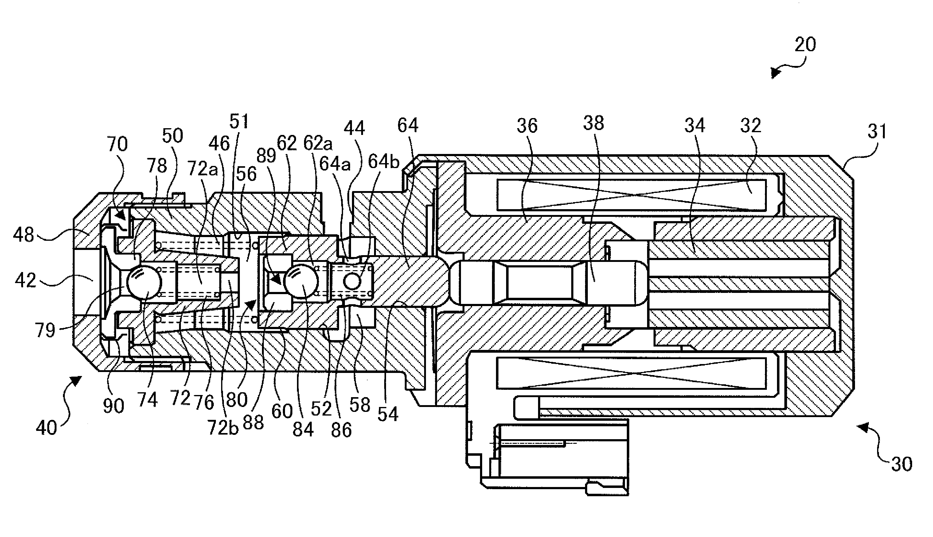
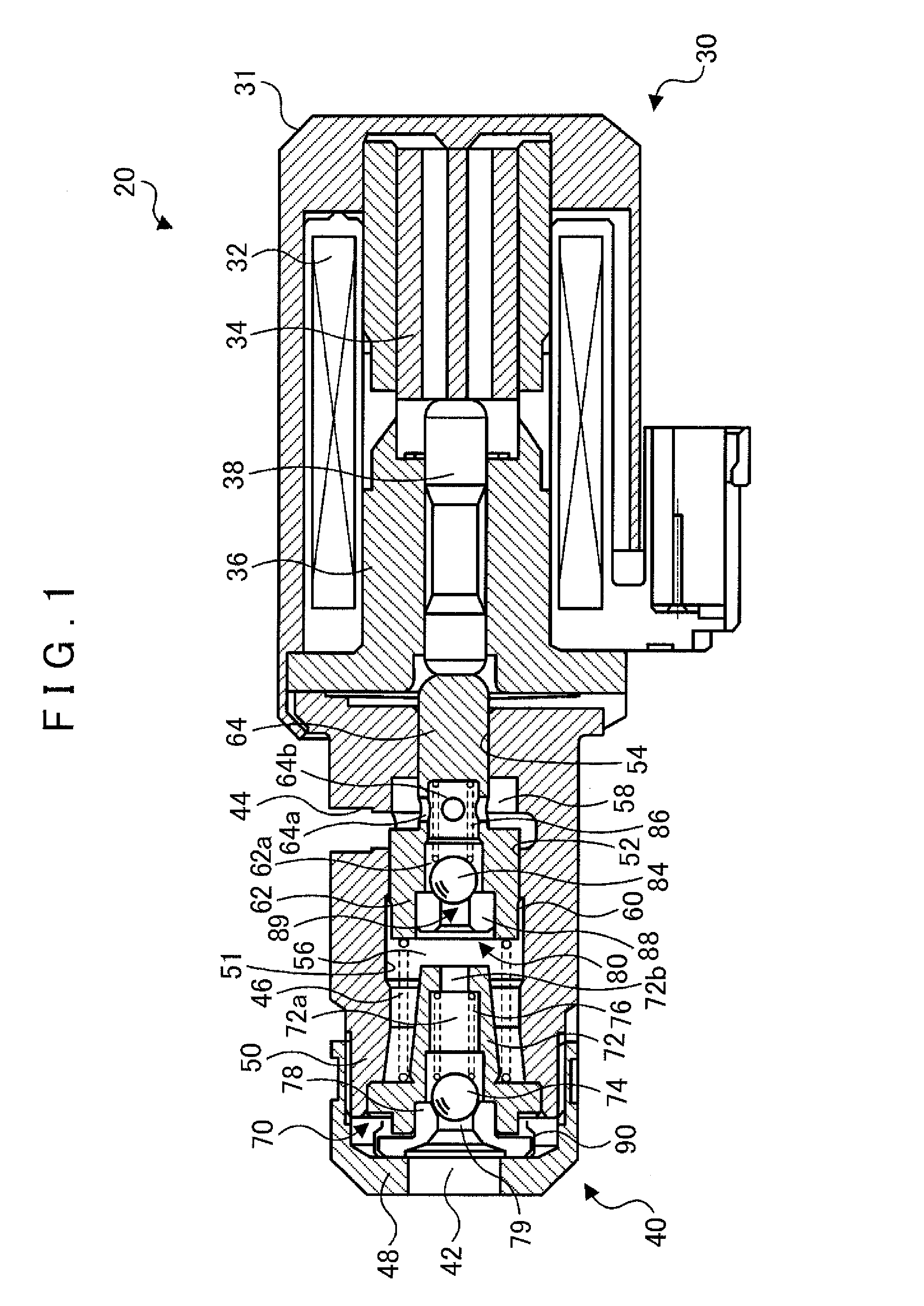
[0026]FIG. 1 is a diagram showing a schematic configuration of an electromagnetic pump 20 according to an embodiment of the present invention. The electromagnetic pump 20 according to the embodiment includes a solenoid portion 30 that generates an electromagnetic force, and a pump portion 40 actuated by the electromagnetic force of the solenoid portion 30. The electromagnetic pump 20 may be formed as a part of a hydraulic control device provided in a vehicle incorporating an engine and an automatic transmission to hydraulically drive friction engagement elements (clutches and brakes) included in the automatic transmission.
[0027]The solenoid portion 30 includes a solenoid case 31 that is a bottomed cylindrical member, an electromagnetic coil 32, a plunger 34 that serves as a movable element, and a core 36 that serves as a stationary element. The electromagnetic coil 32, the plunger 34, and the core 36 are disposed i...
PUM
 Abstract
Description
Claims
Application Information