Stator for electric rotating machine

Active Publication Date: 2011-07-21
DENSO CORP
View PDF4 Cites 24 Cited by
  • Summary
  • Abstract
  • Description
  • Claims
  • Application Information

AI Technical Summary

Benefits of technology

[0012]With the above configuration, when the stator is received in a housing of the electric rotating machine, the joint will not interfere with the inner surface of the housing because the inner surface will first interfere with the crossover part.

Problems solved by technology

However, the thus-formed insulating layer is weaker than the insulating coats of the electric wires which are formed on the electric conductors in the

Method used


Image

  • Stator for electric rotating machine
  • Stator for electric rotating machine
  • Stator for electric rotating machine

Examples


Embodiment Construction

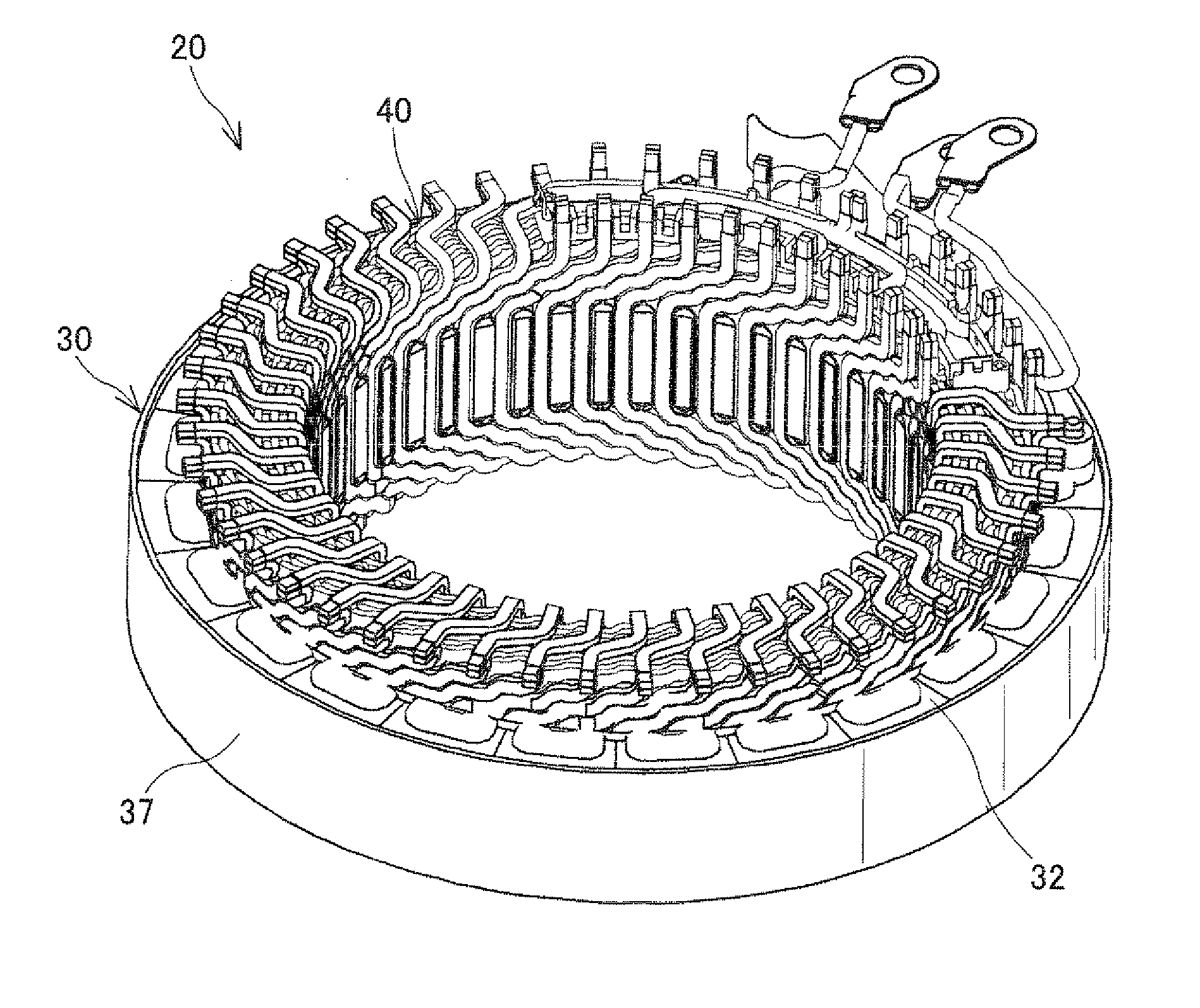
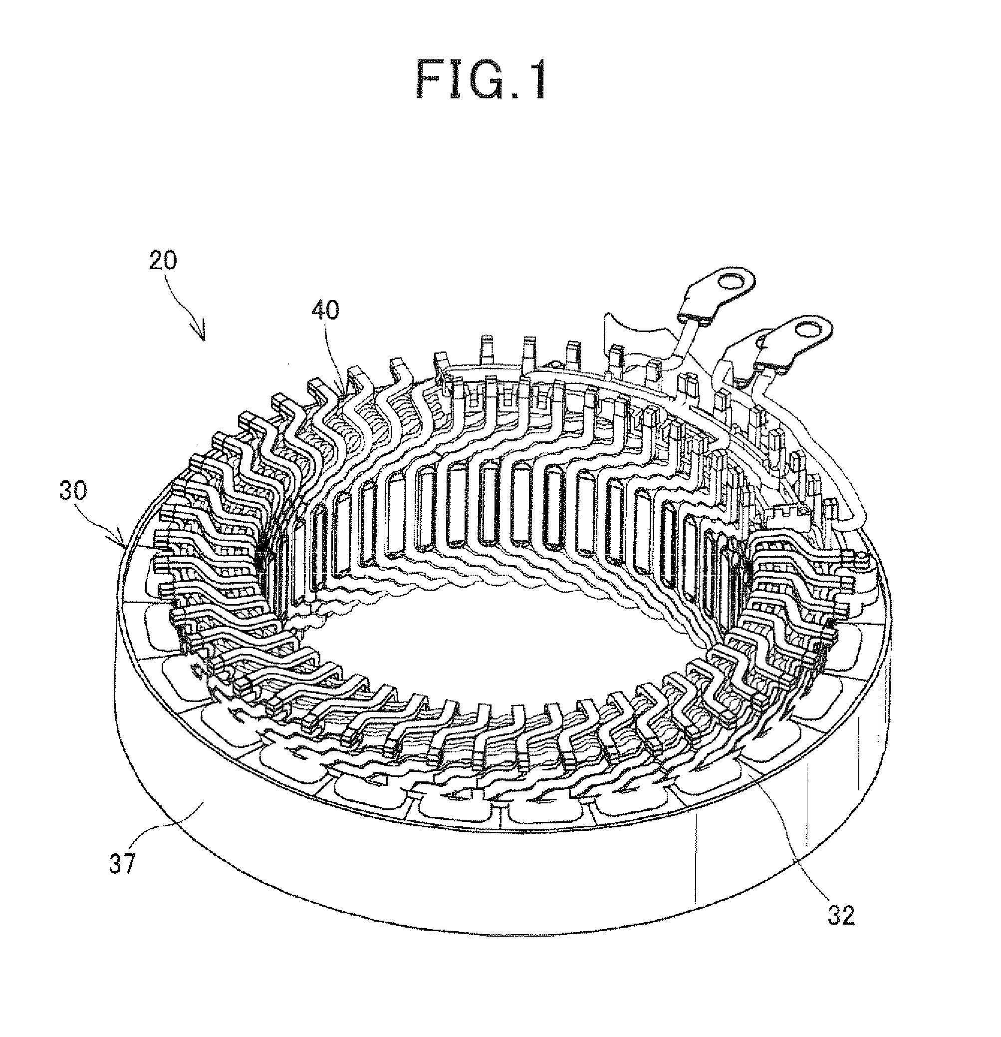
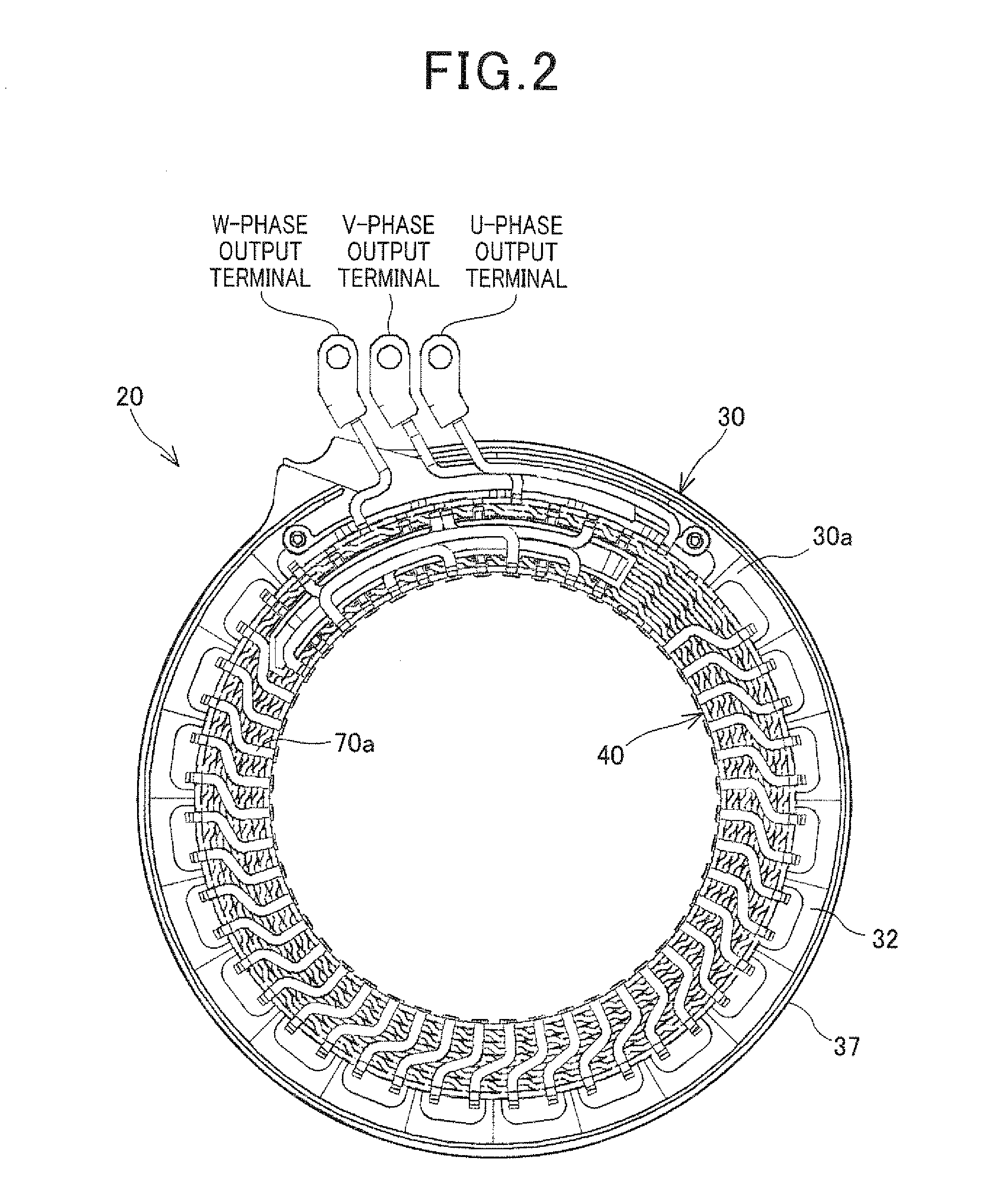
[0046]FIGS. 1-3 together show the overall configuration of a stator 20 according to an embodiment of the invention.

[0047]The stator 20 is designed for use in, for example, an electric rotating machine which is configured to function both as an electric motor and as an electric generator in a motor vehicle. The electric rotating machine further includes a rotor (not shown) that is rotatably disposed so as to be surrounded by the stator 20. The rotor includes a plurality of permanent magnets that form a plurality of magnetic poles on a radially outer periphery of the rotor to face a radially inner periphery of the stator. The polarities of the magnetic poles alternate between north and south in the circumferential direction of the rotor. In addition, in the present embodiment, the number of the magnetic poles formed in the rotor is equal to eight (i.e., four north poles and four south poles).

[0048]As shown in FIGS. 1-3, the stator 20 includes a hollow cylindrical stator core 30 and a ...


PUM


Abstract

A stator includes a stator coil formed of electric wires which include a joined pair of first and second electric wires. The first electric wire has a lead portion led out from the radially inner periphery of a first slot of a stator core and including a crossover part. The crossover part crosses over an axial end face of an end part of the stator coil from the radially inside to the radially outside of the axial end face; the end part protrudes from an axial end face of the stator core. The second electric wire has a lead portion led out from the radially outer periphery of a second slot of the stator core. The lead portions of the electric wires are joined together with a joint formed therebetween. The joint is positioned closer to the axial end face of the stator core than the crossover part is.

Description

CROSS-REFERENCE TO RELATED APPLICATION[0001]This application is based on and claims priority from Japanese Patent Application No. 2010-11042, filed on Jan. 21, 2010, the content of which is hereby incorporated by reference in its entirety into this application.BACKGROUND OF THE INVENTION[0002]1. Technical Field of the Invention[0003]The present invention relates to stators for electric rotating machines that are used in, for example, motor vehicles as electric motors and electric generators.[0004]2. Description of the Related Art[0005]Conventionally, there are known stators for electric rotating machines which include a hollow cylindrical stator core and a stator coil mounted on the stator core.[0006]The stator core has a plurality of slots that are formed in the radially inner surface of the stator core and spaced in the circumferential direction of the stator core. The stator coil is formed by joining a plurality of electric wires. Each of the electric wires includes a plurality o...

Claims


Application Information

Patent Timeline
IPC IPC(8): H02K3/28
CPCH02K3/12H02K3/50H02K3/28
Inventor KOIKE, AKIHITOKATOH, MITSURUYOSHIDA, MASASHI
Owner DENSO CORP
Why Eureka
Try Eureka