Fuse box system and method

a fuse box and fuse technology, applied in the direction of circuit breakers, circuit breakers for excess current, protection switches, etc., can solve the problems of tripping circuit breakers, load is inactive, blown fuses,

Inactive Publication Date: 2011-07-21
HUSS ROY ALLEN
View PDF19 Cites 52 Cited by
  • Summary
  • Abstract
  • Description
  • Claims
  • Application Information

AI Technical Summary

Benefits of technology

[0030]To provide a fuse box system that prohibi...

Problems solved by technology

Inherent in all these prior art approaches is the limitation that when a fuse “blows” or a circuit breaker trips there is generally little if any visual indication that the circuit has been compromised, other than the possibility that the load is inactive in instances where the load may provide a visual indication of circuit activity (electric lights, motors, etc.).
This generally creates a problem in locating blown fuses and tripped circuit breakers in system configu...

Method used


Image

  • Fuse box system and method
  • Fuse box system and method
  • Fuse box system and method

Examples


Embodiment Construction

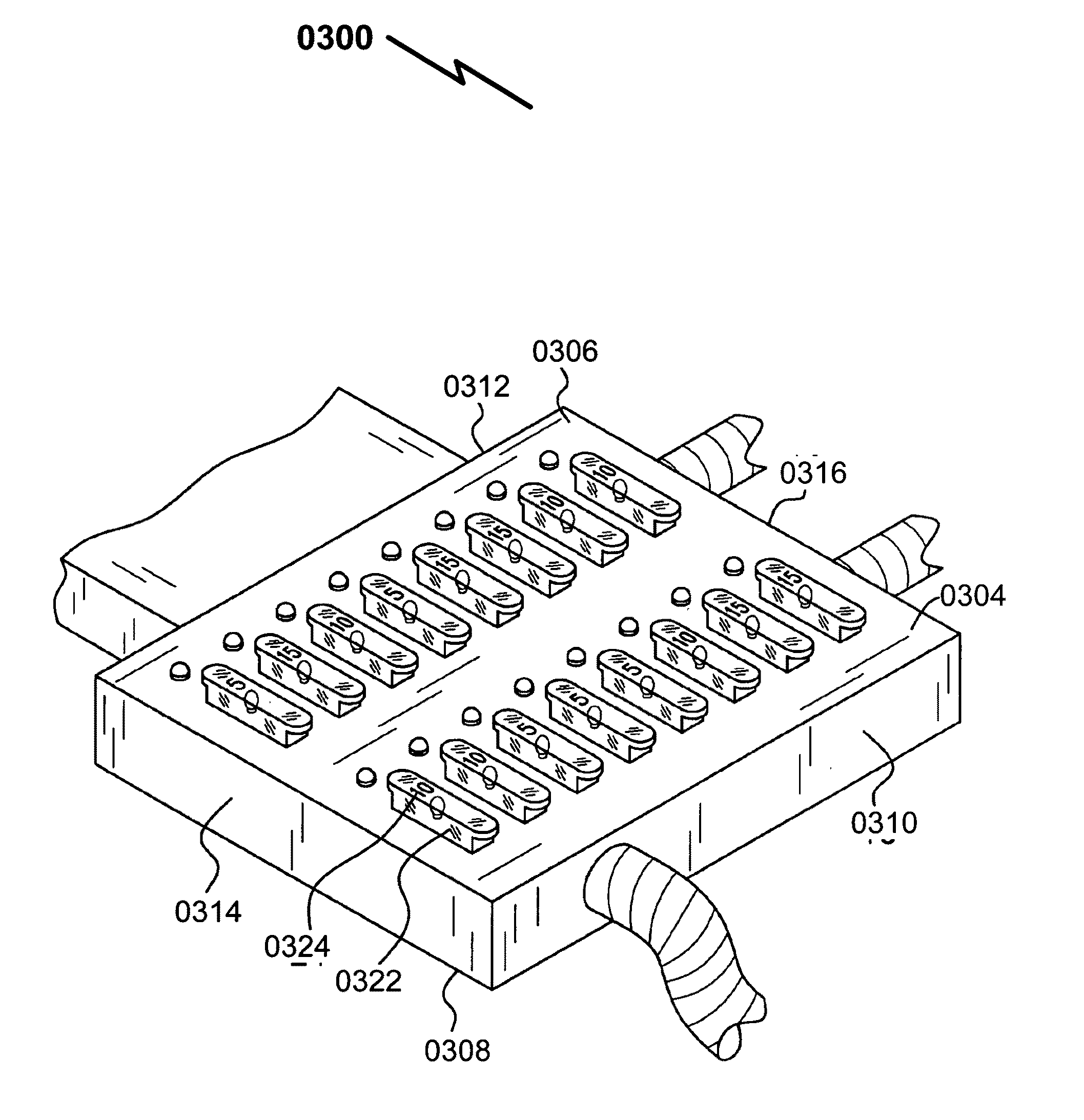
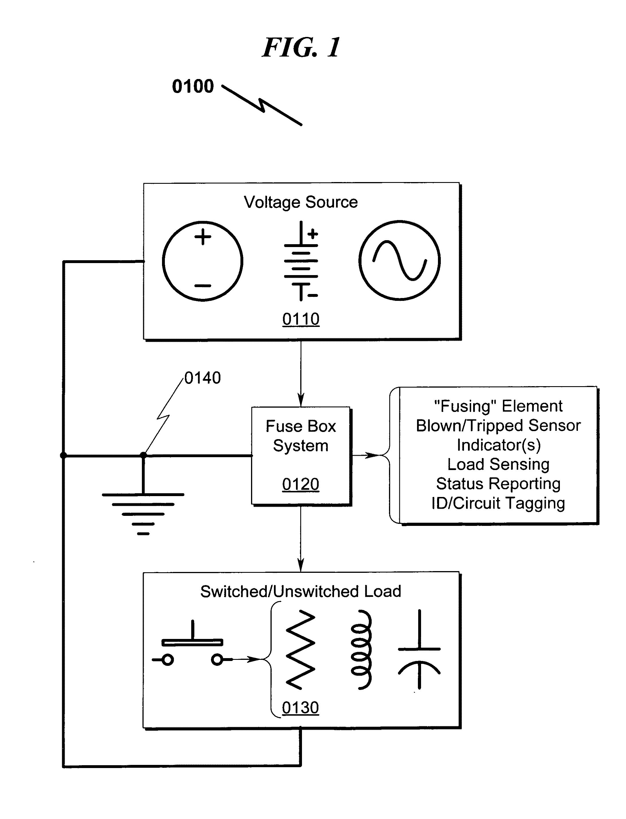
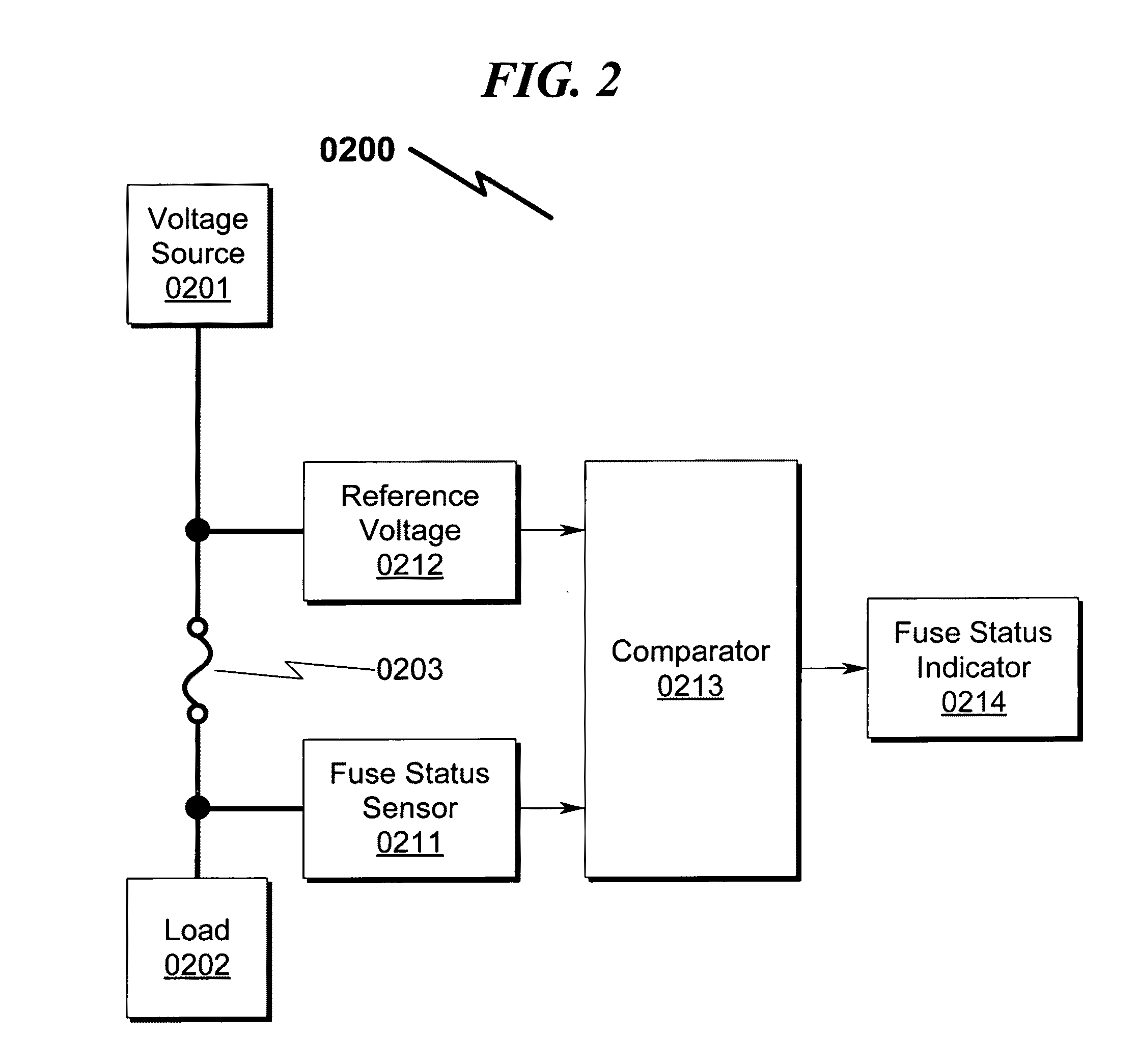
[0096]While the present invention is susceptible of embodiment in many different forms, there is shown in the drawings and will herein be described in detailed preferred embodiment of the present invention with the understanding that the present disclosure is to be considered as an exemplification of the principles of the present invention and is not intended to limit the broad aspect of the present invention to the embodiment illustrated.

[0097]The numerous innovative teachings of the present application will be described with particular reference to the presently preferred embodiment, wherein these innovative teachings are advantageously applied to the particular problems of a FUSE BOX SYSTEM AND METHOD. However, it should be understood that this embodiment is only one example of the many advantageous uses of the innovative teachings herein. In general, statements made in the specification of the present application do not necessarily limit any of the various claimed inventions. Mo...


PUM


Abstract

A fuse box system and method providing for visual and/or remote sensing of interrupted fusing elements is disclosed. The system incorporates LEDs and/or remote sensing apparatus to permit indication of a “blown” fuse and/or circuit protection breaker. This system may be configured for both polarized and/or non-polarized applications and generally provides for indicator illumination when a fuse/breaker is blown. Some preferred embodiments may incorporate current sourcing technologies to permit operation of the system over wide range of system voltages, as well as provisions for wired and/or RF/wireless interrogation of the fuse/breaker status. Alternate embodiments including systems/methods to permit remote sensing of fuse status and/or circuit current monitoring, and may be retrofit within existing fuse/breaker panel systems in some configurations.

Description

CROSS REFERENCE TO RELATED APPLICATIONS[0001]This patent application is a Continuation-In-Part of patent application Ser. No. 12 / 931,120 for FUSE BOX SYSTEM AND METHOD, filed on Jan. 25, 2011, which was a Continuation-In-Part of application Ser. No. 12 / 728,981 filed on Mar. 22, 2010. Applicants claim benefit pursuant to 35 U.S.C. §120 and hereby incorporate by reference these patent applications.[0002]Application Ser. No. 12 / 931,120 is a Continuation-In-Part of patent application Ser. No. 12 / 728,981 for FUSE BOX SYSTEM, filed on Mar. 22, 2010, which was a Continuation-In-Part of application Ser. No. 12 / 169,467 filed on Jul. 8, 2008. Applicants claim benefit pursuant to 35 U.S.C. §120 and hereby incorporate by reference these patent applications.[0003]Application Ser. No. 12 / 169,467 matured to U.S. Pat. No. 7,683,752 and issued on Mar. 23, 2010 and was a Continuation-In-Part of application Ser. No. 11 / 620,243 filed on Jan. 5, 2007, now abandoned. Applicants claim benefit pursuant to ...

Claims


Application Information

Patent Timeline
IPC IPC(8): H01H71/00H01H85/02
CPCH01H2085/208H01H85/32
Inventor HUSS, ROY ALLENDUFOUR, JERRY ANTHONYKLUGHART, KEVIN MARK
Owner HUSS ROY ALLEN
Why Eureka
Try Eureka