Tyre having a member with an offset antenna

Active Publication Date: 2011-07-21
MICHELIN & CO CIE GEN DES ESTAB MICHELIN
View PDF13 Cites 83 Cited by
  • Summary
  • Abstract
  • Description
  • Claims
  • Application Information

AI Technical Summary

Benefits of technology

[0007]An aspect of the invention is to alleviate this drawback

Problems solved by technology

However, the presence of the non-stretchable chip embedded inside the sidewall is the cause of disruption of the stress fields that are in the sidewall.
However, these antennas are not suitable for withstanding the additional stresses created by

Method used


Image

  • Tyre having a member with an offset antenna
  • Tyre having a member with an offset antenna
  • Tyre having a member with an offset antenna

Examples


Embodiment Construction

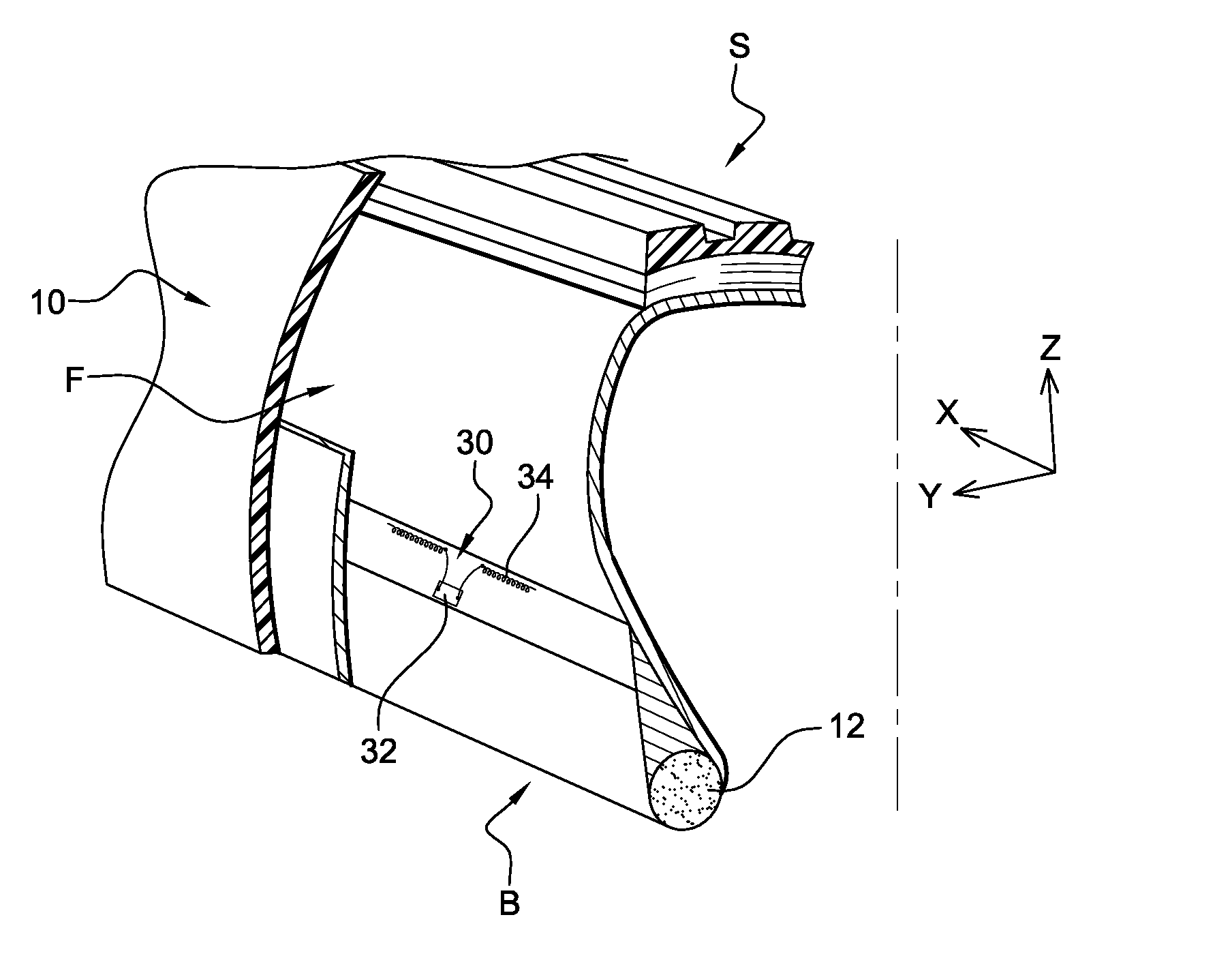
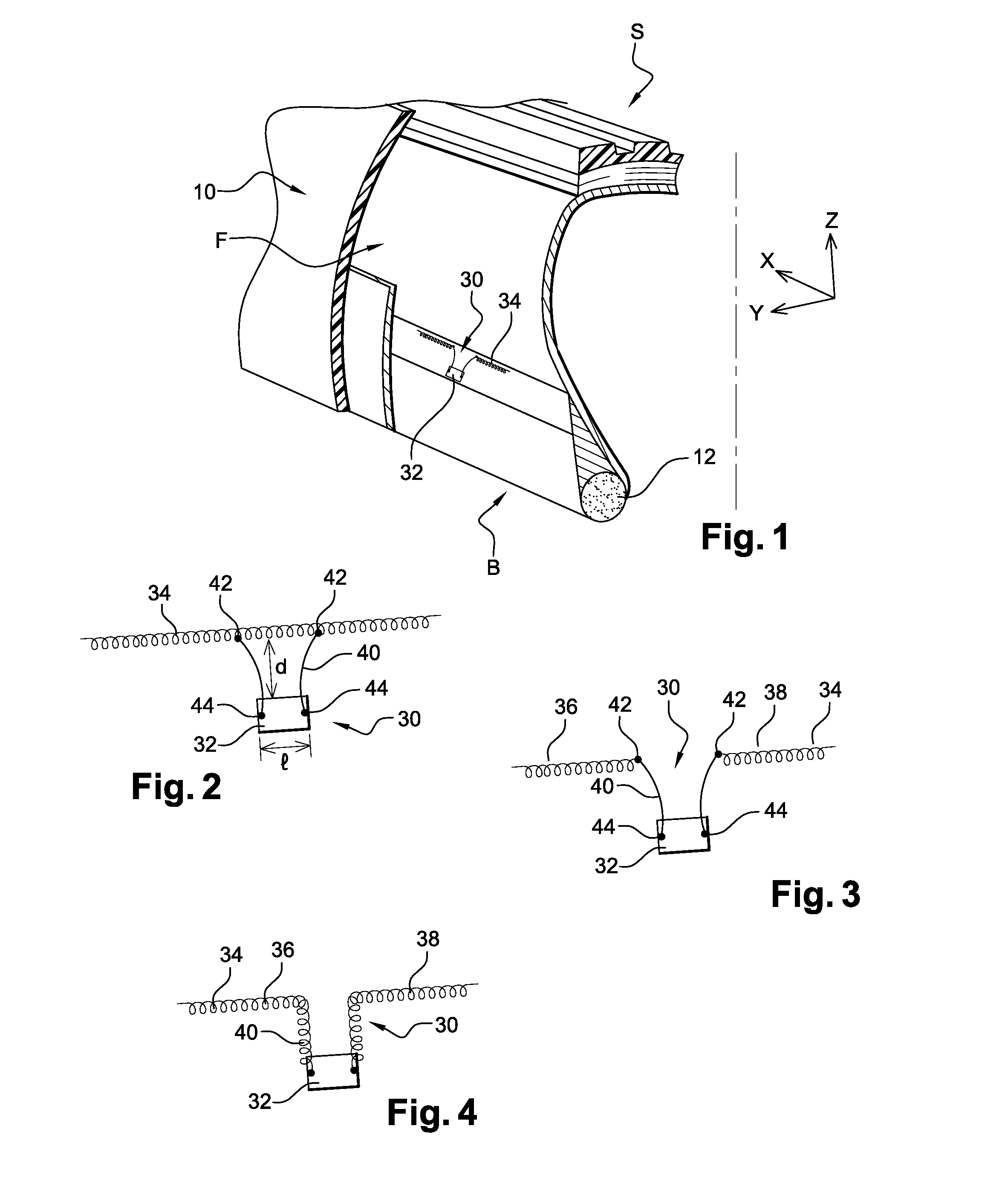
[0031]In the figures are shown axes X, Y, and Z that are orthogonal with one another in the usual orientations, radial (Z), axial (Y), and circumferential (X) of a tyre.

[0032]FIGS. 1, 7, and 8 show a tyre according to an embodiment of the invention, designated by the general reference 10. In this instance, the tyre 10 is intended to be mounted on a wheel of a motor vehicle of the lorry type.

[0033]Conventionally, the tyre 10 comprises a crown S extended by two sidewalls F (only one of which is shown in the figures). The radially internal portion of the sidewall F comprises a bead B and the radially external portion of the sidewall F comprises a shoulder E situated on the border between the sidewall F and the crown S.

[0034]A bead wire 12 is embedded in the bead B.

[0035]The bead wire 12 is of revolution about a reference axis. This reference axis, substantially parallel to the direction Y, is substantially indistinguishable from an axis of revolution of the tyre.

[0036]The crown S compr...


PUM


Abstract

A motor-vehicle tyre includes a sidewall and a member with an electronic device, a generally and substantially linear-shaped rectilinear wire antenna, and means of electrical connection between the wire antenna and the electronic device. The member is embedded in the sidewall in an arrangement such that the antenna is oriented circumferentially with respect to the tyre and the connection means is oriented in a radial direction of the tyre. The wire antenna is integrally offset radially on one side of the electronic device.

Description

FIELD OF THE INVENTION[0001]The invention relates to the field of motor-vehicle tyres, notably tyres incorporating an electronic member for controlling or measuring certain parameters.BACKGROUND OF THE INVENTION[0002]In the rest of the description, the general shape of the tyre is similar to a torus. Therefore, directions that are axial, radial, and circumferential to the tyre are defined relative to this torus.[0003]Document WO 2004 / 011285 discloses a member comprising an electronic device such as an RFID (Radio Frequency Identification) chip to which a linear antenna is connected comprising two branches connected on either side of the chip.[0004]The electric member disclosed in this document is supported by a sidewall of the tyre in a configuration such that the wire antenna is oriented in a circumferential direction of the tyre.[0005]When the tyre is running on the ground, and notably when its tread is in the contact area, the sidewalls of the tyre deform, which generates circumf...

Claims


Application Information

Patent Timeline
IPC IPC(8): H01Q1/32
CPCB29D2030/0077H01Q1/2241B60C23/0493B60C23/0452
Inventor MYATT, DAVID
Owner MICHELIN & CO CIE GEN DES ESTAB MICHELIN
Why Eureka
Try Eureka