
Imaging lens, optical apparatus equipped therewith, and method for manufacturing imaging lens

a technology of optical apparatus and imaging lens, which is applied in the direction of lenses, manufacturing tools, instruments, etc., can solve the problems of large moving amount needed for focusing, and large optical system, so as to reduce ghost images and flares, improve optical performance, and reduce optical system size

Active Publication Date: 2011-07-21
NIKON CORP
View PDF3 Cites 10 Cited by
  • Summary
  • Abstract
  • Description
  • Claims
  • Application Information

AI Technical Summary

Benefits of technology

[0009]The present invention is made in view of the above-described problems and has an object to provide an imaging lens capable of obtaining excellent optical performance from infinity to a close object with downsizing the optical system with reducing ghost images and flare.
[0015]The present invention makes it possible to provide an imaging lens capable of obtaining excellent optical performance from infinity to a close object with downsizing the optical system with reducing ghost images and flare, an optical apparatus equipped with the imaging lens, and a method for manufacturing the imaging lens.

Problems solved by technology

However, in the four-lens-group configuration, because of the large number of the lens group the optical system tends to become large.
Moreover, in the two-lens-group configuration, although the optical system can easily be downsized, a moving amount necessary for focusing becomes large.
At the same time, there has been a problem that reflection light producing ghost images and flare tends to be generated from optical surfaces of such an imaging lens.

Method used


Image

  • Imaging lens, optical apparatus equipped therewith, and method for manufacturing imaging lens
  • Imaging lens, optical apparatus equipped therewith, and method for manufacturing imaging lens
  • Imaging lens, optical apparatus equipped therewith, and method for manufacturing imaging lens

Examples


example 1

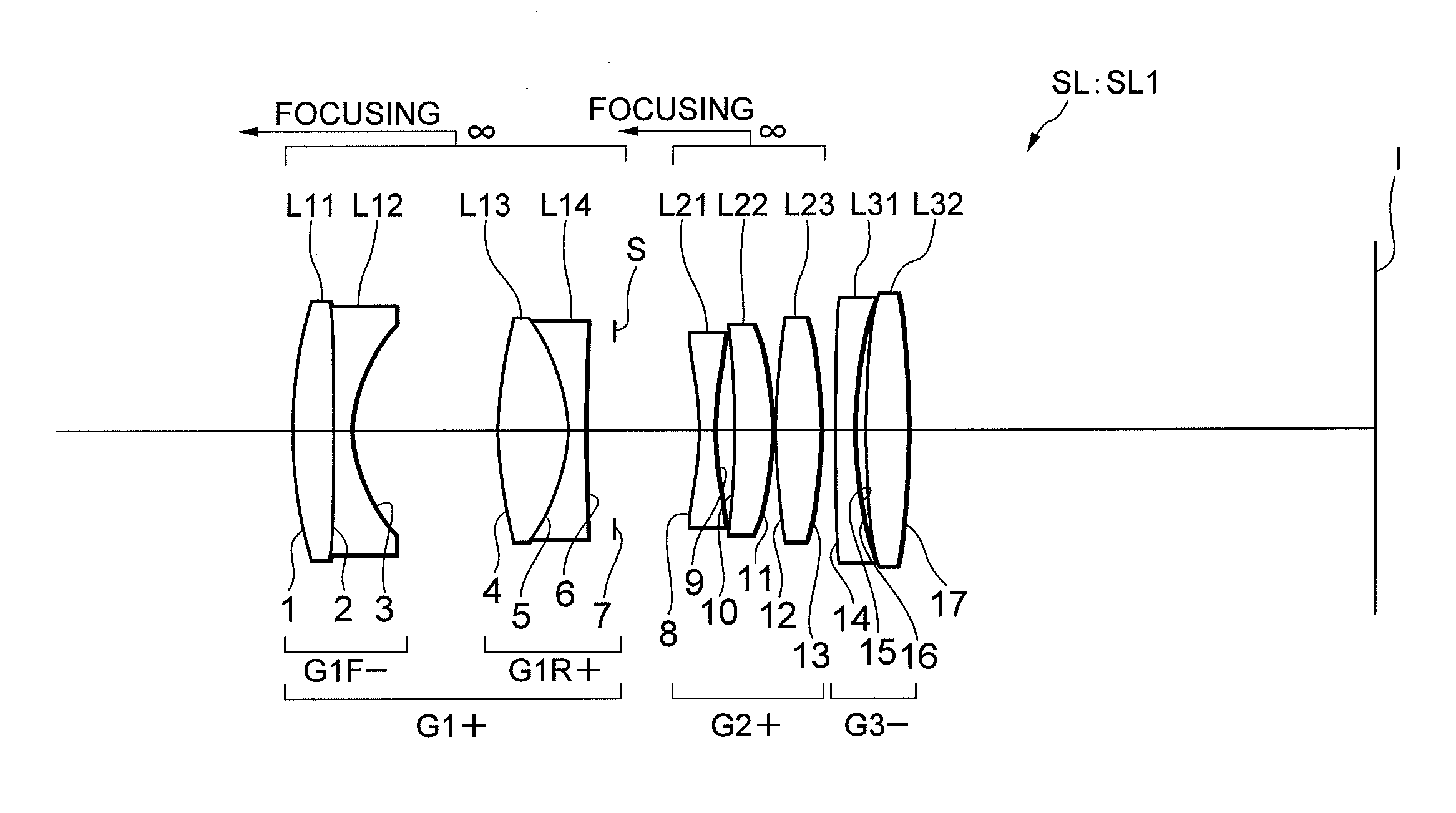
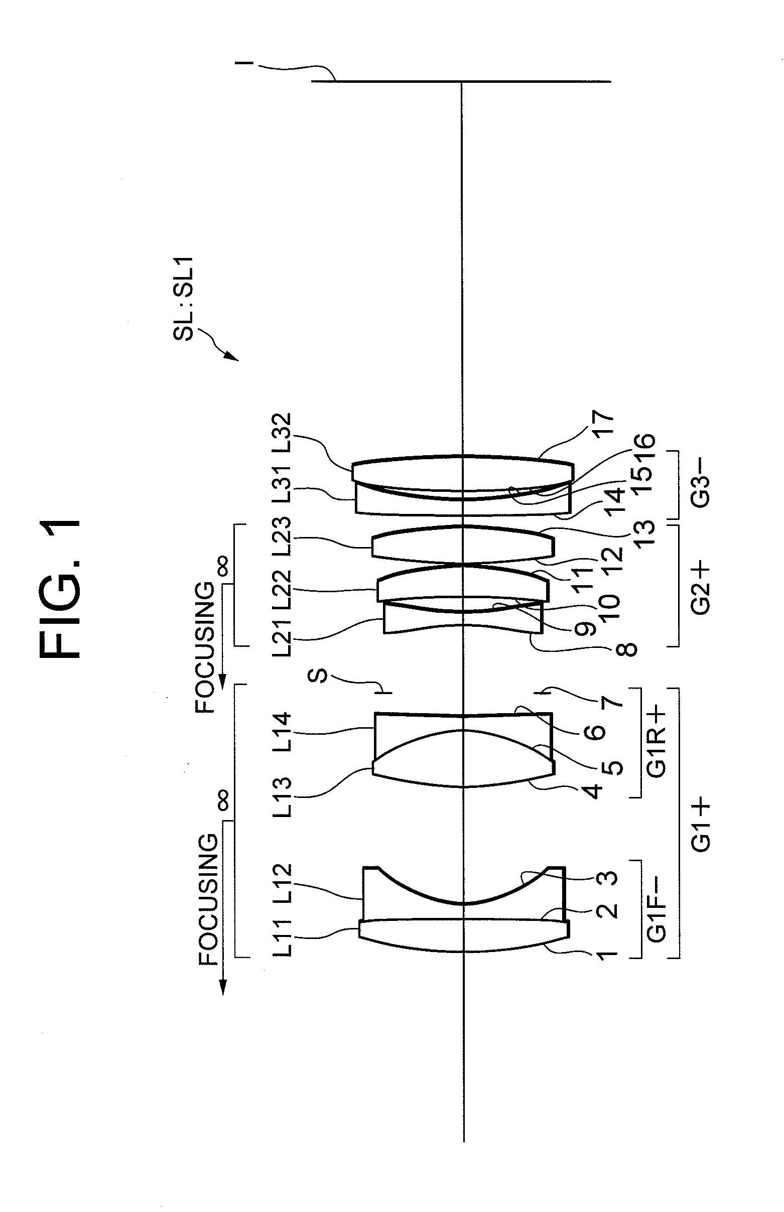
[0088]As shown in FIG. 1, the imaging lens SL1 is composed of, in order from an object side, a first lens group G1 having positive refractive power, an aperture stop S, a second lens group G2 having positive refractive power, and a third lens group G3 having negative refractive power. Upon focusing from an infinity object to a close object, the first lens group G1 and the second lens group G2 (focusing lens group) are moved independently toward the object side along the optical axis, thereby focusing on an object disposed at a finite distance.

[0089]The first lens group G1 is composed of, in order from the object side, a front group G1F having negative refractive power, and a rear group G1R having positive refractive power. The front group G1F is composed of a cemented lens constructed by, in order from the object side, a double convex positive lens L11 cemented with a double concave negative lens L12. The cemented lens may be constructed by a positive meniscus lens cemented with a n...

example 2

[0102]FIG. 4 is a sectional view showing a lens configuration of an imaging lens SL2 according to Example 2 of the present application. The imaging lens SL2 according to Example 2 is composed of, in order from an object side, a first lens group G1 having positive refractive power, an aperture stop S, a second lens group G2 having positive refractive power, and a third lens group G3 having negative refractive power. Upon focusing from an infinity object to a close object, the first lens group G1 and the second lens group G2 (focusing lens group) are moved independently toward the object side along the optical axis, thereby focusing on an object disposed at a finite distance.

[0103]The first lens group G1 is composed of, in order from the object side, a front group G1F having negative refractive power, and a rear group G1R having positive refractive power. The front group G1F is composed of, in order from the object side, a positive meniscus lens L11 having a convex surface facing the ...

example 3

[0109]FIG. 6 is a sectional view showing a lens configuration of an imaging lens SL3 according to Example 3 of the present application. The imaging lens SL3 according to Example 3 is composed of, in order from an object side, a first lens group G1 having positive refractive power, an aperture stop S, a second lens group G2 having positive refractive power, and a third lens group G3 having negative refractive power. Upon focusing from an infinity object to a close object, the first lens group G1 and the second lens group G2 (focusing lens group) are moved independently toward the object side along the optical axis, thereby focusing on an object disposed at a finite distance.

[0110]The first lens group G1 is composed of, in order from the object side, a front group G1F having negative refractive power, and a rear group G1R having positive refractive power. The front group G1F is composed of, in order from the object side, a double convex positive lens L11 having a smaller absolute valu...


PUM

PropertyMeasurementUnit
refractive index ndaaaaaaaaaa
refractive poweraaaaaaaaaa
refractive index ndaaaaaaaaaa

Abstract

An imaging lens SL comprising, in order from an object side: a first group G1 having positive refractive power; an aperture stop S; a second group G2 having positive refractive power; and a third group G3 having negative refractive power; upon focusing from infinity to a close object, the first group and the second group moving independently along an optical axis toward the object side, the first group including, in order from the object side, a front group having negative refractive power, and a rear group having positive refractive power, and the front group consisting of, in order from the object side, a positive lens and a negative lens, thereby providing an imaging lens capable of obtaining excellent optical performance upon focusing from infinity to a close object, with downsizing the optical system with a simple lens construction, an optical apparatus and a method for manufacturing the imaging lens.

Description

[0001]The disclosure of the following priority applications are herein incorporated by reference:[0002]Japanese Patent Application No. 2010-009580 filed on Jan. 20, 2010, and[0003]Japanese Patent Application No. 2010-272975 filed on Dec. 7, 2010.BACKGROUND OF THE INVENTION[0004]1. Field of the Invention[0005]The present invention relates to an imaging lens, an optical apparatus equipped with the imaging lens, and a method for manufacturing the imaging lens.[0006]2. Related Background Art[0007]In an optical system capable of carrying out excellent optical performance from infinity to a close object, there have been proposed various lens types such as, for example, a four-lens-group configuration disclosed in, for example, Japanese Patent Application Laid-Open No. 2009-063715, and a two-lens-group configuration disclosed in, for example, Japanese Patent Application Laid-Open No. 2007-086308. Regarding such an optical system capable of realizing excellent optical performance upon focus...

Claims


Application Information

Patent Timeline
Patent Type & Authority Applications(United States)
IPC IPC(8): G02B9/12G02B1/11G02B13/18B23P17/00G02B7/105
CPCG02B1/113Y10T29/49982G02B13/02
Inventor MOURI, MOTOHISATANAKA, ISSEI
Owner NIKON CORP
Learn More