Packet relay apparatus and method of relaying packet

a relay apparatus and packet technology, applied in electrical apparatus, digital transmission, data switching networks, etc., can solve problems such as congestion of communication, overflow of communication relay apparatus, interference with smooth communication,

Inactive Publication Date: 2011-07-21
ALAXALA NETWORKS
View PDF9 Cites 41 Cited by
  • Summary
  • Abstract
  • Description
  • Claims
  • Application Information

AI Technical Summary

Benefits of technology

[0017]An object of the present invention is to provide technology that is able to provide a unique packet drop control in a packet relay apparatus adopting a multi-stage queue structure.

Problems solved by technology

Extremely heavier communication traffic or an excess communication request significantly exceeding the capacity of a communication relay apparatus may interfere with smooth communication.
This is generally called congestion of communication.
The congestion occurs in any communication including the today's Internet communication.
The communication traffic over the acceptable range of the packet relay apparatus may cause congestion.
This control scheme is readily implemented but causes a slow start of packet retransmission by simultaneous packet drop and gives only a poorer throughput than expected under TCP / IP communication.
The RED algorithm has more difficulty in implementation than the Tail Drop algorithm but allows packets to be gradually dropped at a rate corresponding to the queue length.
Both these variant control schemes are highly functional to enable packet drop control with different priorities set for the respective applications of packets but require rather complicated information management with regard to the respective applications.
In this internal configuration, congestion of a queue at the former stage may cause the queue monitoring the overall buffer memory capacity may be overflowed first.
For example, in a simple scheme of storing packets in a queue (queuing) if there is still room to the overall buffer memory capacity, accumulation of packets in a specific queue may lead to a packet overflow of a queue at a latter stage.
This restrains other queues from using the buffer memory and thereby interferes with smooth communication of the other queues.
This significantly lowers the overall throughput of the network.
It is thus highly probable that congestion simultaneously affects all the queues and causes packets to be simultaneously dropped from all the queues.
This technique does not actualize flexible drop control for the users having different priorities.

Method used


Image

  • Packet relay apparatus and method of relaying packet
  • Packet relay apparatus and method of relaying packet
  • Packet relay apparatus and method of relaying packet

Examples


first embodiment

A. First Embodiment

A1. Apparatus Configuration

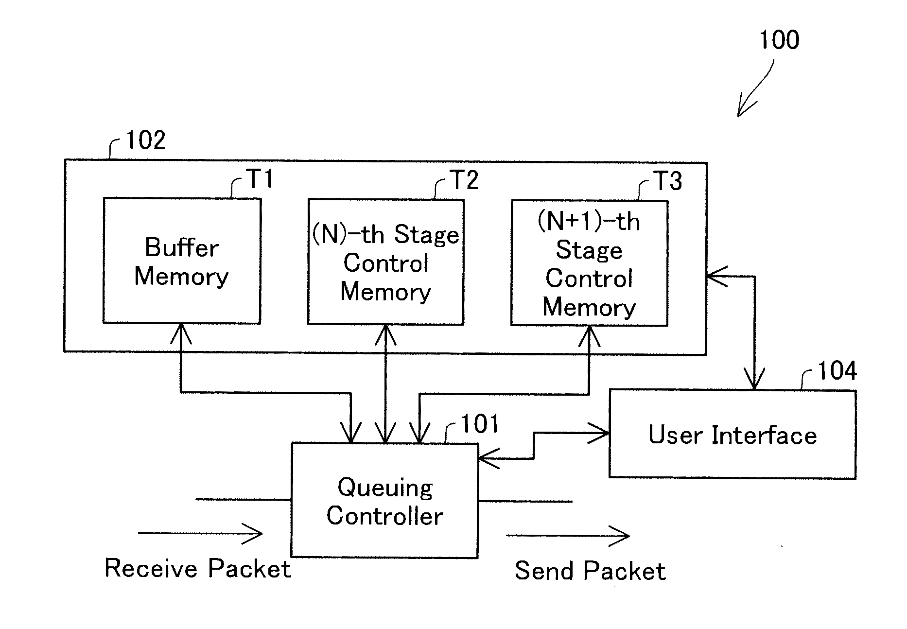
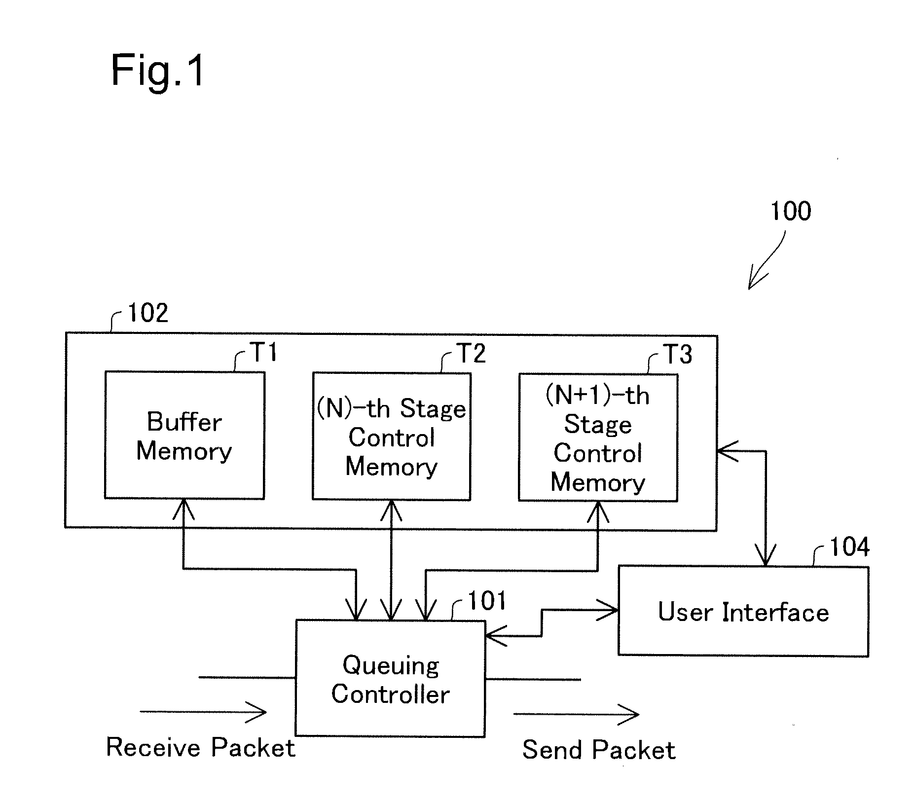
[0047]FIG. 1 is an explanatory diagrammatic representation of the configuration of a packet relay apparatus 100 with focusing on its queuing-relevant portion according to one embodiment of the present invention. The packet relay apparatus 100 internally has queues at two different stages for packet communication. In the following description of this embodiment, a former stage and a latter stage in the packet relay apparatus 100 are expressed as an (N)-th stage and an (N+1)-th stage.

[0048]The packet relay apparatus 100 includes a queuing controller 101 configured to perform queuing control of packets based on control information of the respective queues, a memory group 102 configured to store control information and packets, and a user interface 104. The queuing controller 101 includes a CPU, a ROM, and a RAM (all not shown). The CPU reads and executes a program loaded on the RAM to perform the queuing control. The memory group 102 includ...

second embodiment

B. Second Embodiment

[0083]FIG. 9 is a conceptual diagrammatic representation of a multi-stage queue structure in a second embodiment. The difference from the multi-stage queue structure of the first embodiment described above is only drop classes adopted for the (N+1)-th stage queue drop / non-drop determination. The apparatus configuration and the processing flow of the (N)-th stage queue drop / non-drop determination are identical with those of the first embodiment. The drop classes are used to classify packets by the priority and are set to have different priorities.

[0084]In this embodiment, the queuing controller 101 classifies each packet into one of four drop classes, based on the state of an identified queue at the (N)-th stage which the packet belongs to. The queuing controller 101 then makes packets classified into a drop class with the higher priority unlikely to be dropped, compared with packets classified into a drop class with the lower priority. More specifically, the queu...

third embodiment

C. Third Embodiment

[0091]FIG. 11 is an explanatory diagrammatic representation of the control information stored in the (N)-th stage control memory T2 in a third embodiment. In the first and the second embodiments discussed above, the queuing controller 101 uses the queue length QLEN(N) of an identified queue at the (N)-th stage for computation of the drop probability DP and specification of a drop class. Alternatively the queuing controller 101 may measure communication traffic TRAF(N) of an identified queue at the (N)-th stage and use the measured communication traffic TRAF(N) as the control information for the (N+1)-th stage queue drop / non-drop determination. More specifically, the queuing controller 101 may compute the drop probability DP or specify the drop class in order to increase the preference of decision of a drop for a packet belonging to a queue with heavy communication traffic TRAF by the (N+1)-th stage queue drop / non-drop determination. This scheme also enables the (N...


PUM


Abstract

The packet relay apparatus is provided. The packet relay apparatus includes a receiver that receives a packet; and a determiner that determines to drop the received packet without storing the received packet into a queue among the multi-stage queue. The determiner determines to drop the received packet at a latter stage, based on former-stage queue information representing a state of a queue at any former stage which the received packet belongs to and latter-stage queue information representing a state of a queue at the latter stage which the received packet belongs to.

Description

CROSS-REFERENCE TO RELATED APPLICATIONS[0001]The present application claims priority to Japanese Patent Application No. 2010-011037 filed on Jan. 21, 2010, the disclosure of which is hereby incorporated by reference in its entirety.BACKGROUND OF THE INVENTION[0002]1. Field of the Invention[0003]The present invention relates to a packet relay apparatus configured to relay a packet and a method of relaying a packet.[0004]2. Description of the Related Art[0005]Extremely heavier communication traffic or an excess communication request significantly exceeding the capacity of a communication relay apparatus may interfere with smooth communication. This is generally called congestion of communication. The congestion occurs in any communication including the today's Internet communication.[0006]The Internet communication generally receives and sends data in units of packets. Switches and routers are typical examples of packet relay apparatuses configured to relay such packets. The packet re...

Claims


Application Information

Patent Timeline
Patent Type & Authority Applications(United States)
IPC IPC(8): H04L12/56H04L12/801H04L12/861H04L12/911
CPCH04L47/17H04L47/29H04L49/9036H04L47/32H04L47/30
Inventor YAMADA, TAKAHIROHINOSUGI, HIDEKI
Owner ALAXALA NETWORKS
Why Eureka
Try Eureka