
Molding machine

a molding machine and mold technology, applied in the field of molding machines, can solve the problem that the conventional molding machine is not capable of precisely molding containers

Active Publication Date: 2011-07-21
JIH HUANG MACHINERY INDAL
View PDF5 Cites 4 Cited by
  • Summary
  • Abstract
  • Description
  • Claims
  • Application Information

AI Technical Summary

Benefits of technology

[0005]Therefore, the object of the present invention is to provide a molding machine that includes molds operable to move close to or away from each other, and that is able to mold containers precisely.

Problems solved by technology

Therefore, the conventional molding machine is not capable of molding the containers precisely.

Method used


Image

  • Molding machine
  • Molding machine
  • Molding machine

Examples


Embodiment Construction

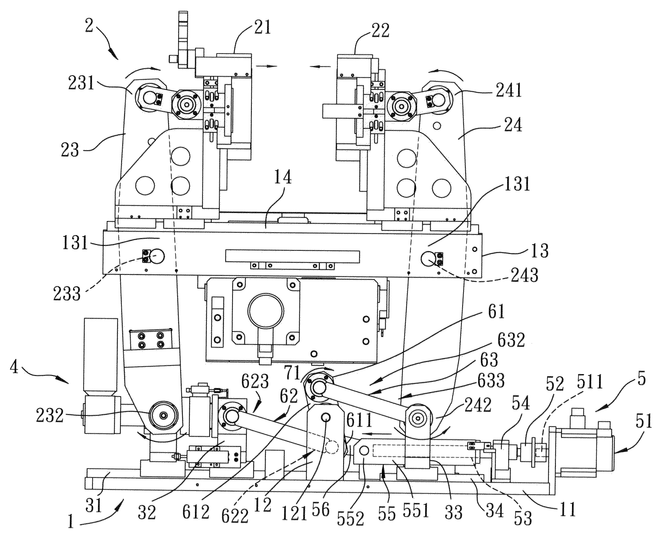
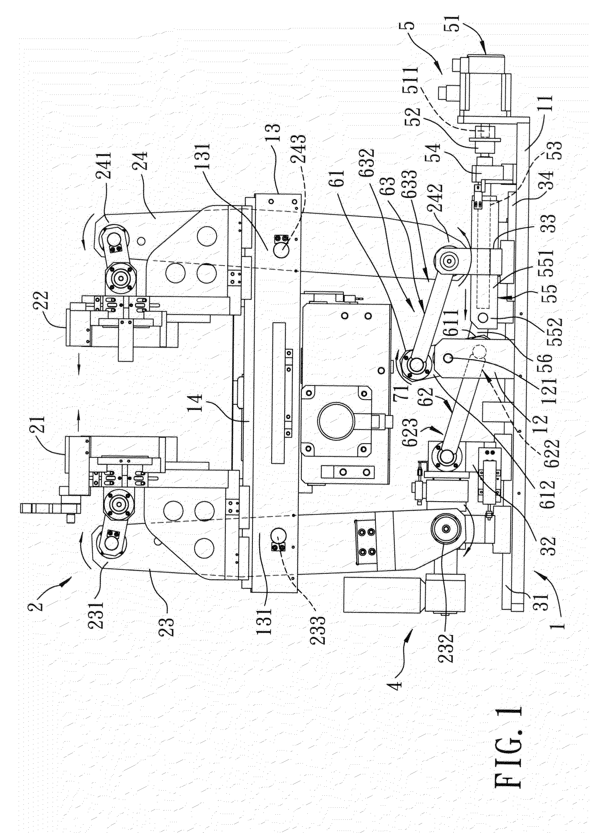
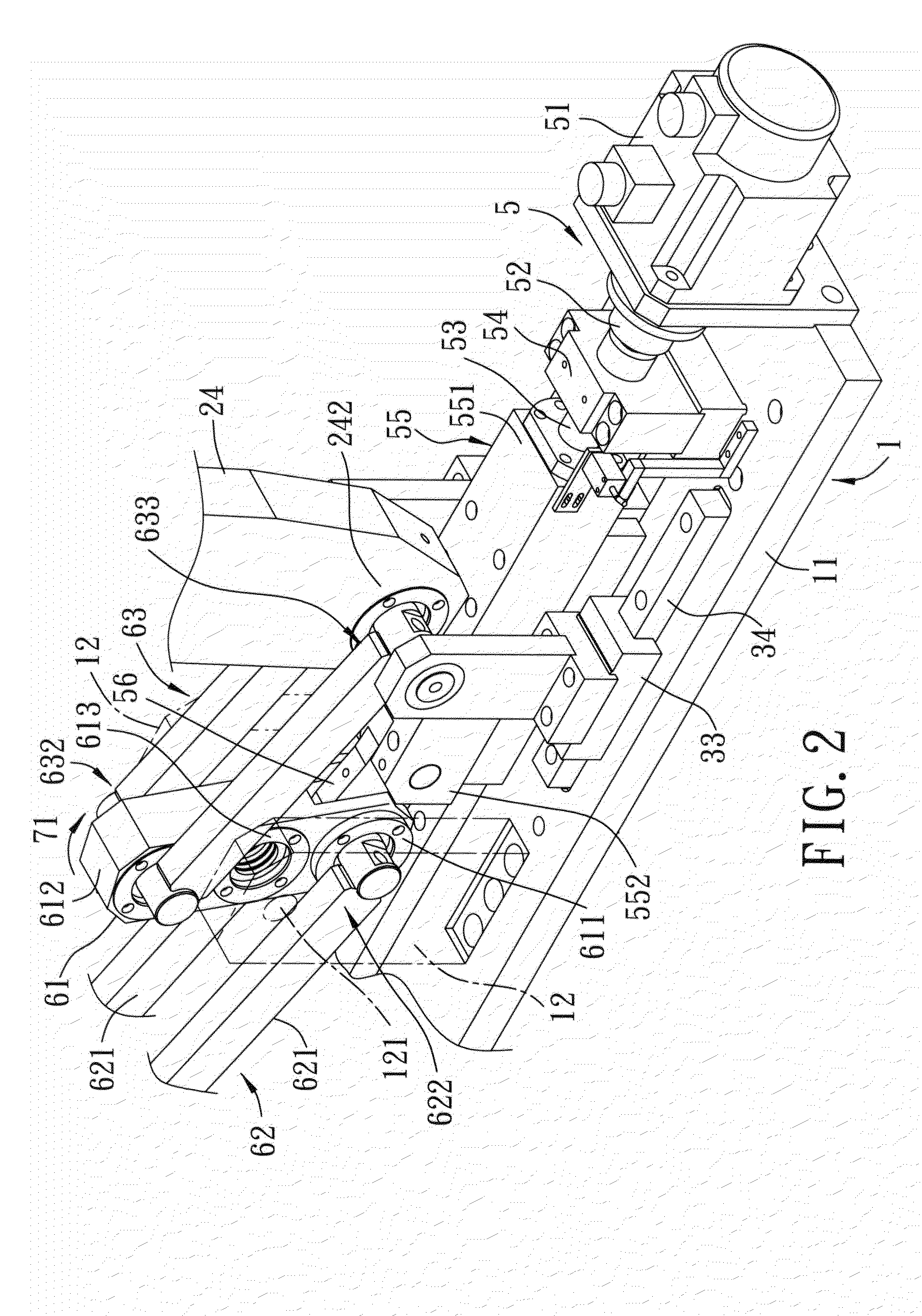
[0011]As shown in FIGS. 1 to 3, the preferred embodiment of a molding machine according to the present invention comprises a base unit 1, left and right molds 21, 22, and left and right holding arms 23, 24.

[0012]The base unit 1 includes a base seat 11, a pair of mounting parts 12 mounted on the base seat 11 and spaced apart from each other in a front-rear direction, a mold-mounting seat 13 disposed over the base seat 11, and a plurality of mold-engaging rails 14 mounted on the mold-mounting seat 13, extends in the left-right direction, and spaced-apart from each other in the front-rear direction (only one is visible in FIG. 1). Each of the mounting parts 12 has a coupling section 121. The mold-mounting seat 13 has left and right pivot mounts 131 that are spaced-apart from each other in a left-right direction.

[0013]The left and right molds 21, 22 are disposed on the base unit 1, and engage and movable along the mold-engaging rails 14.

[0014]The left and right holding arms 23, 24 are m...


PUM

PropertyMeasurementUnit
momentumaaaaaaaaaa
thicknessaaaaaaaaaa
thickaaaaaaaaaa

Abstract

A molding machine includes two holding arms mounted on a base unit, connected respectively to two molds, and operable to move the molds between a mold closing state and a mold opened state. The molding machine further includes an adjusting seat mounted on the base unit and movable relative to a threaded shaft that is rotated by a power supply, a swing arm connected pivotally to the adjusting seat, a linkage unit having opposite end parts that are connected pivotally and respectively to a pivot portion of the swing arm and one of the holding arms, and another linkage unit having opposite end parts that are connected pivotally and respectively to another pivot portion of the swing arm and the other one of the holding arms. The swing arm is swingable through the movement of the adjusting seat so as to swing the holding arms by virtue of the linkage units.

Description

BACKGROUND OF THE INVENTION[0001]1. Field of the Invention[0002]The invention relates to a molding machine, for molding products, such as containers.[0003]2. Description of the Related Art[0004]Japanese Patent No. P2004-255598A discloses conventional molding machine that includes a stationary mold and a movable mold. The movable mold is operable to move close to or away from the stationary mold for molding containers. However, when the movable mold is moved to couple with the stationary mold, the stationary mold is pushed by the momentum of the movable mold, and may be slightly moved from its normal position instead of being stationary relative to the movable mold. Therefore, the conventional molding machine is not capable of molding the containers precisely.SUMMARY OF THE INVENTION[0005]Therefore, the object of the present invention is to provide a molding machine that includes molds operable to move close to or away from each other, and that is able to mold containers precisely.[0...

Claims


Application Information

Patent Timeline
Patent Type & Authority Applications(United States)
IPC IPC(8): B28B7/04
CPCB29C49/56B29C49/4236B29C49/42362B29C49/5602B29C49/561
Inventor LIN, PING-JUNGLIN, PO-HUNGLIN, PO-HANG
Owner JIH HUANG MACHINERY INDAL
Learn More