
Shrink sleeve for an article closure

a technology for wrapping sleeves and articles, applied in the field of wrapping sleeves for containers, can solve the problems of label adhesive to the side surface of the closure, label decoration, and various reasons that have not been applied to the side of the closure, and achieve the effect of easy volatilization, greater torsional force, and added aesthetics of the label

Inactive Publication Date: 2011-07-21
MULTI COLOR CORP
View PDF105 Cites 3 Cited by
  • Summary
  • Abstract
  • Description
  • Claims
  • Application Information

AI Technical Summary

Benefits of technology

The solution provides a durable, aesthetically enhanced label that remains attached to the closure despite torsional forces, maintaining decoration and preventing slippage, while also offering a comfortable touch and thermal barrier properties.

Problems solved by technology

However, while adhesives may be applied to the portion of the shrink sleeve that contacts the body portion of the article, they are not applied to the portion of the shrink sleeve that contacts the closure of the article (i.e., the tamper-evident portion of the shrink sleeve “above” any perforation).
Further, large closures, such as those found on containers of laundry detergent, often include ridges and grooves, which make it difficult for a label to adhere to the side surface of the closure.
And, if any shrink sleeve were shrunk against such a closure, the shrink film would conform to the multiple ridges and grooves, thereby disrupting the appearance of any decoration thereon.
However, labels, such as the decorated pressure-sensitive labels, have not been applied to the sides of closures for various reasons.
One reason is that the side surfaces of closures often include features like ridges or flanges that disrupt the ability of the label to adhere to, or otherwise associate with, the side of the closure, and also may interfere with the presentation of any decoration.
Thus, any label information is lost.
Further, the appearance of an article having a label or other decoration removed due to these torsional forces may be unaesthetic.

Method used


Image

  • Shrink sleeve for an article closure
  • Shrink sleeve for an article closure
  • Shrink sleeve for an article closure

Examples


Embodiment Construction

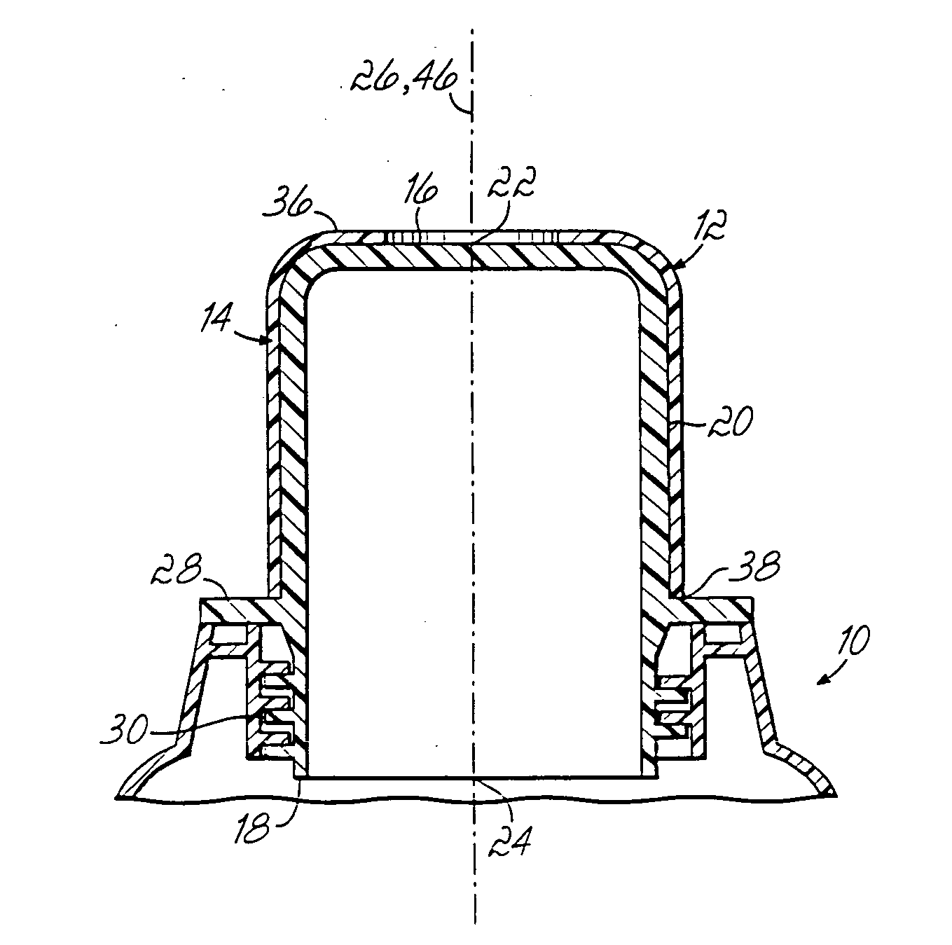
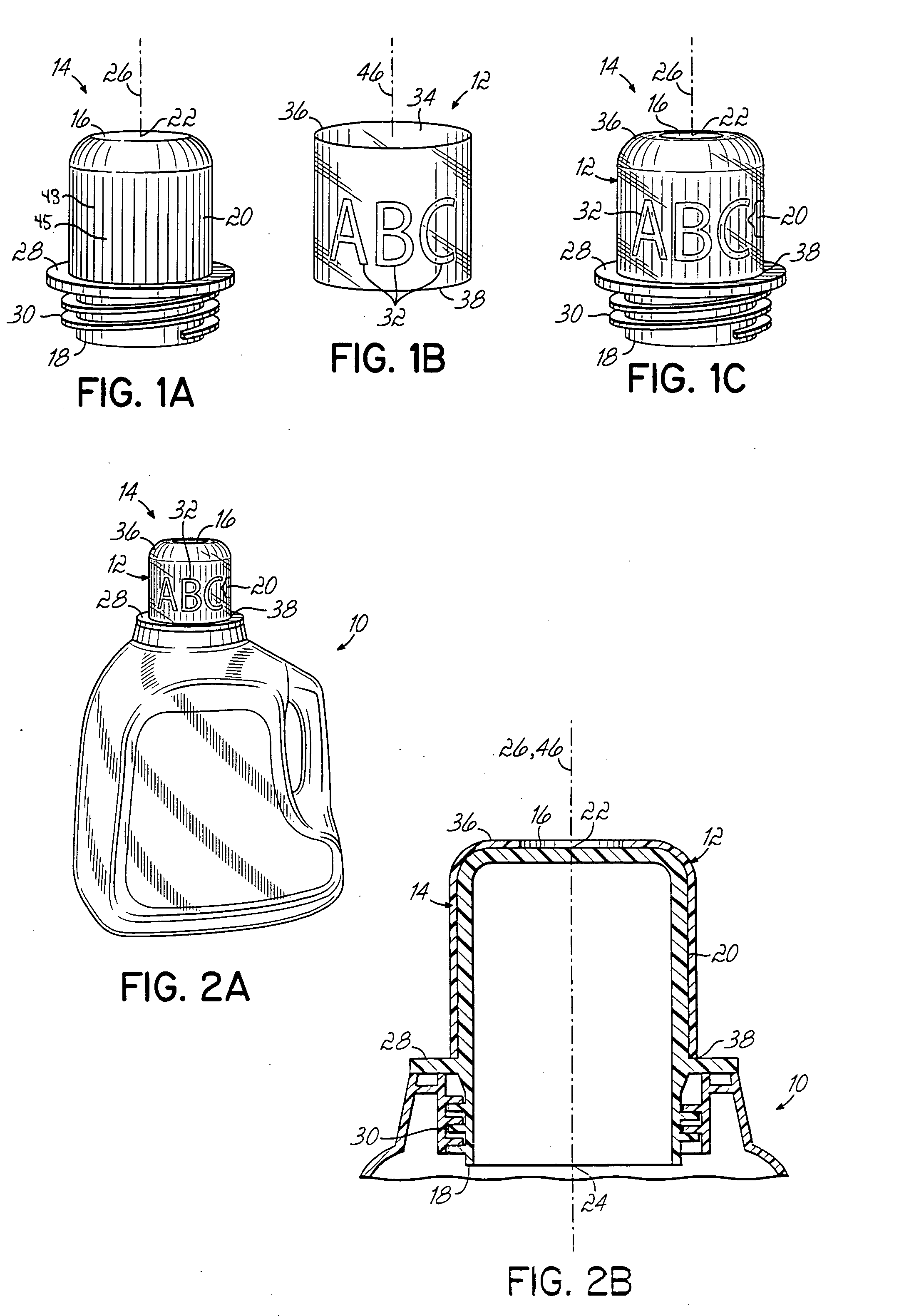
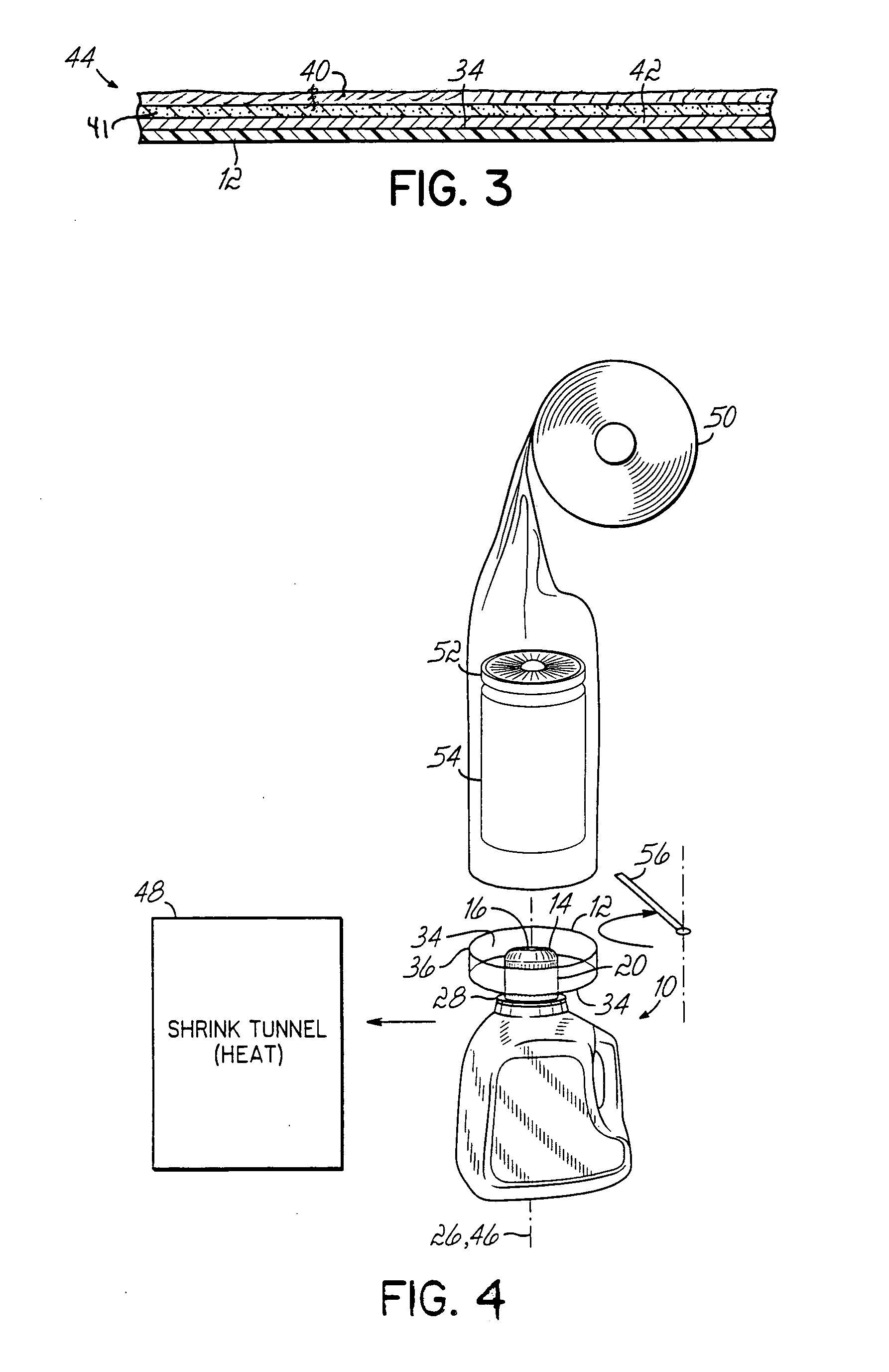
[0029] Referring now to the Figures, the present invention provides a labeled article 10 for packaging an item or items. This labeled article 10 includes a shrink sleeve 12 and an article 10 including a closure 14. In particular, and referring to FIGS. 1A-1C, in a first aspect, the present invention provides a decorated closure 14 for an article 10, such as a container used to package an item or items. The decorated closure 14 includes a shrink sleeve 12 and a closure 14 for an article 10. The closure 14 has a top end 16, a bottom end 18, and a side surface 20. The closure 14 may further include a centerpoint 22 of the top end 16 and a centerpoint 24 of the bottom end 18 with a longitudinal axis 26 passing therethrough. As shown in FIG. 1A, the closure 14 includes a flange 28 and screw threads 30 proximal its bottom end 18. It should be recognized that the closure 14 including flange 28 and screw threads 30 is merely exemplary, and any type of closure 14 may be used.

[0030] As shown...


PUM

PropertyMeasurementUnit
temperaturesaaaaaaaaaa
diameteraaaaaaaaaa
diameteraaaaaaaaaa

Abstract

The present invention provides a shrink sleeve for use on a closure of an article. The present invention does so by providing a decorated closure for an article, such as a container, used to package an item or items. The decorated closure includes a shrink sleeve and a closure for an article. The closure has a top end, a bottom end, and a side surface. The closure may further include a centerpoint of the top end and a centerpoint of the bottom end with a longitudinal axis passing therethrough. The shrink sleeve is shrunk around at least the side surface of the article, and the shrink sleeve is a laminate that includes a heat-activatable expandable layer.

Description

CROSS-REFERENCE TO RELATED APPLICATIONS [0001] This application is a continuation-in-part of U.S. patent application Ser. No. 11 / 253,044, entitled “Shrink Sleeve for an Article Closure,” filed Oct. 18, 2005, the disclosure of which is incorporated by reference herein in its entirety.FIELD OF THE INVENTION [0002] The present invention relates to shrink films for various articles, and in particular, to shrink sleeves for containers having closures. BACKGROUND OF THE INVENTION [0003] Shrink films, such as shrink sleeves and shrink wraps, are used in labeling, often as an alternative to pressure-sensitive labels, heat-transfer labels, in-mold labels, and other labels. Shrink labeling involves sizing a shrink film, which may be a tubular shrink sleeve, to a particular article. Then one shrinks the film to snugly wrap the article within the shrink sleeve. The shrinking process is generally accomplished by the application of heat or steam to the shrink sleeve. Further processing may includ...

Claims


Application Information

Patent Timeline
Patent Type & Authority Applications(United States)
IPC IPC(8): F16B4/00
CPCB65C3/065B65C3/20B65D51/245B65D55/0854Y10T428/1352Y10T428/28Y10T428/1328Y10T156/103G09F3/04
Inventor ALBENICE, PHILIP J.VOELKER, JOHNLAPRADE, JEAN-PAULDONATELLI, JEANGEURTSEN, JOHN W.
Owner MULTI COLOR CORP
Learn More