Glass roll

a glass film and roll technology, applied in the field of glass film, can solve the problems of glass film easily breaking and remains to be solved, and achieve the effect of inhibiting glass film from breaking

Active Publication Date: 2011-07-21
NIPPON ELECTRIC GLASS CO LTD
View PDF13 Cites 30 Cited by
  • Summary
  • Abstract
  • Description
  • Claims
  • Application Information

AI Technical Summary

Benefits of technology

[0032]According to the present invention described above, in the glass roll utilizing the flanged roll core, the flange and the end portion in the width direction of the glass film are separated from each other, and the cushioning means is arranged between the flange and the end portion in the width direction of the glass film. Thus, it is possible to satisfactorily protect the end portion in the width direction of the glass film. Therefore, it is possible to reliably inhibit the glass film from breaking from the end portion in the width direction thereof as an origin of breakage.

Problems solved by technology

Therefore, as disclosed in Patent Literature 2, even in a case of adopting the glass roll as a package form for a glass film, there is a problem that remains to be solved.
Consequently, the glass film easily breaks.

Method used


Image

  • Glass roll
  • Glass roll
  • Glass roll

Examples


Embodiment Construction

[0052]In the following, embodiments of the present invention are described with reference to the attached drawings.

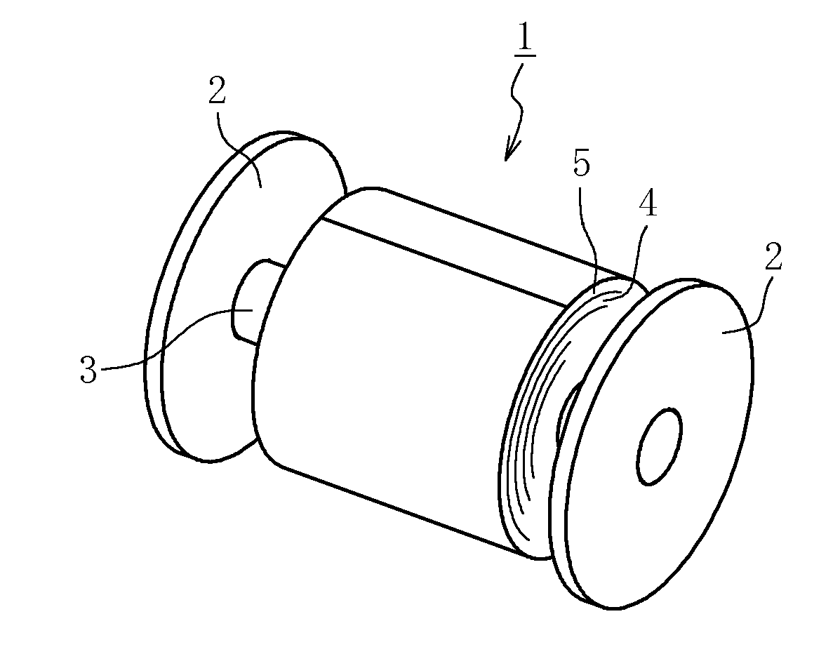
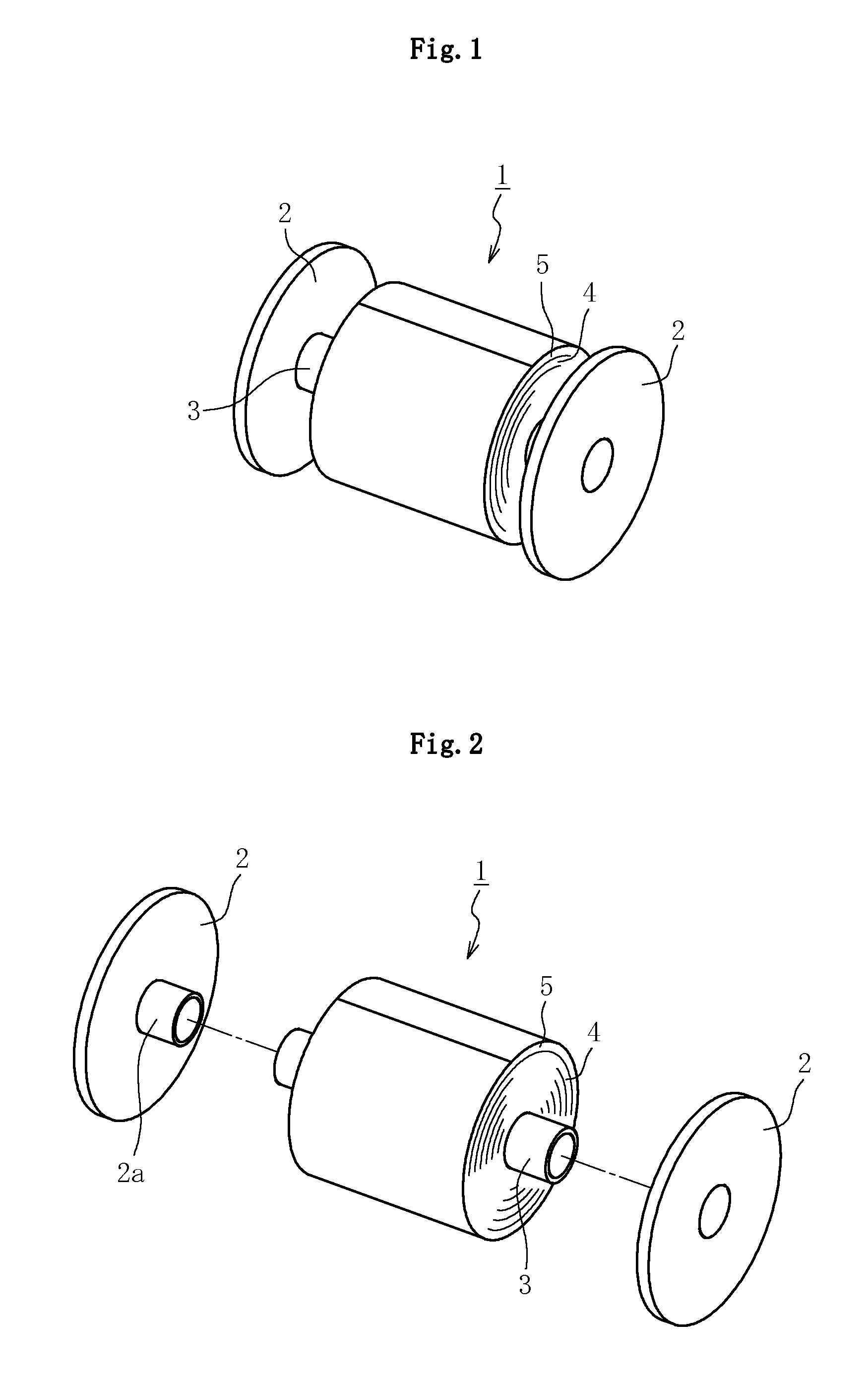
[0053]FIG. 1 is a perspective view illustrating an entire configuration of a glass roll according to a first embodiment of the present invention. A glass roll 1 is formed by winding a glass film 4 and a cushion sheet 5, under a state of being superposed, around a roll core 3 including a flange 2 at each end portion thereof.

[0054]The glass film 4 is glass formed by an overflow downdraw method to have a thickness of from 1 μm to 200 μm (preferably from 10 μm to 100 μm). With the thickness within the above-mentioned numerical range, it is possible to impart, to the glass film 4, appropriate flexibility involving no trouble at the time of winding. Note that, when the thickness of the glass film 4 is less than 1 μm, handling of the glass film is troublesome because of lack of strength. When the thickness of the glass film 4 exceeds 200 μm, satisfactory flexibility is not obt...


PUM

PropertyMeasurementUnit
thicknessaaaaaaaaaa
thicknessaaaaaaaaaa
thicknessaaaaaaaaaa

Abstract

Provided is a glass roll utilizing a flanged roll core, and reliably inhibiting a glass film from breaking from an end portion in a width direction thereof as an origin of breakage. A glass roll (1) is formed by winding a glass film (4) and a cushion sheet (5), under a state of being superposed, around a roll core (3) including a flange (2) at each end portion thereof, in which an end portion in a width direction of the glass film (4) is separated from the flange (2) on each side in the width direction of the glass film (4), and the cushion sheet (5) is extended beyond the end portion in the width direction of the glass film (4) to the flange (2) side, to thereby form an extension portion (5a).

Description

TECHNICAL FIELD[0001]The present invention relates to an improved technology for a package form for a glass film which is used as a glass substrate for a flat panel display and a solar cell, and used as cover glass or the like for an organic light-emitting diode (OLED) lighting.BACKGROUND ART[0002]As is well known in the art, in recent years, there is a demand for further thinning of various glass plates including glass substrates for a flat panel display, such as a liquid crystal display, a plasma display, an organic light-emitting diode (OLED) display, or a field emission display. Along with the demand for the further thinning, as disclosed, for example, in Patent Literature 1, a film-like sheet glass having a thickness of 200 μm or less has been developed.[0003]Further, as disclosed, for example, in Patent Literature 2, as a package form for the above-mentioned sheet glass thinned into a film (hereinafter, referred to as glass film), there is adopted a glass roll formed by windin...

Claims


Application Information

Patent Timeline
Patent Type & Authority Applications(United States)
IPC IPC(8): B32B17/06
CPCB65D57/00B65D85/30Y10T428/24B65D85/672B65D85/48B32B17/10B65D57/005
Inventor TOMAMOTO, MASAHIROETA, MICHIHARUODA, HIDETAKATAKAYA, TATSUYAYAMAZAKI, YASUOTAKIMOTO, HIROSHIISHIBASHI, SHINICHITAKAGI, KEIJINAGATA, DAISUKENAKAMURA, TAKAHIDESAKURABAYASHI, TORUFUJIWARA, KATSUTOSHINODA, MITSUHARUOGISO, YASUHIKOFUJII, TAKAHIDE
Owner NIPPON ELECTRIC GLASS CO LTD
Why Eureka
Try Eureka