Cable with stranded wire pairs

a technology of stranded wires and cables, applied in the direction of cables, insulated conductors, conductors, etc., can solve the problems of simple and space-saving installation, and achieve the effect of satisfying protection

Active Publication Date: 2019-04-02
ROSENBERGER HOCHFREQUENZTECHNIK GMBH & CO KG
View PDF23 Cites 3 Cited by
  • Summary
  • Abstract
  • Description
  • Claims
  • Application Information

AI Technical Summary

Benefits of technology

[0010]In view of the problems described, it is the object of the present invention to make a cable of the type described above more compact and at the same time guarantee a satisfactory protection against external interference and interference caused by adjacent wire pairs.
[0012]In other words, the individual wires of a wire pair are not in each case twisted together; rather, the wire pairs are stranded together around a common stranding center. Also, due to the stranding according to the invention, the mutual paths of the individual wire pairs and the distance from the adjacent wire pairs along the cable are in each case predetermined, so that a predictable, constant crosstalk level per cable unit length can be expected. Moreover, due to the orderly path of the individual wire pairs around the stranding center, the cable can be made more compact and thus also thinner and more space-saving than conventional cables, as a result of which the effort involved in installation and the transport costs can be reduced.

Problems solved by technology

Moreover, a conventional USB 3.0 cable is comparatively thick, which makes simple and space-saving installation difficult.

Method used


Image

  • Cable with stranded wire pairs
  • Cable with stranded wire pairs
  • Cable with stranded wire pairs

Examples


first embodiment

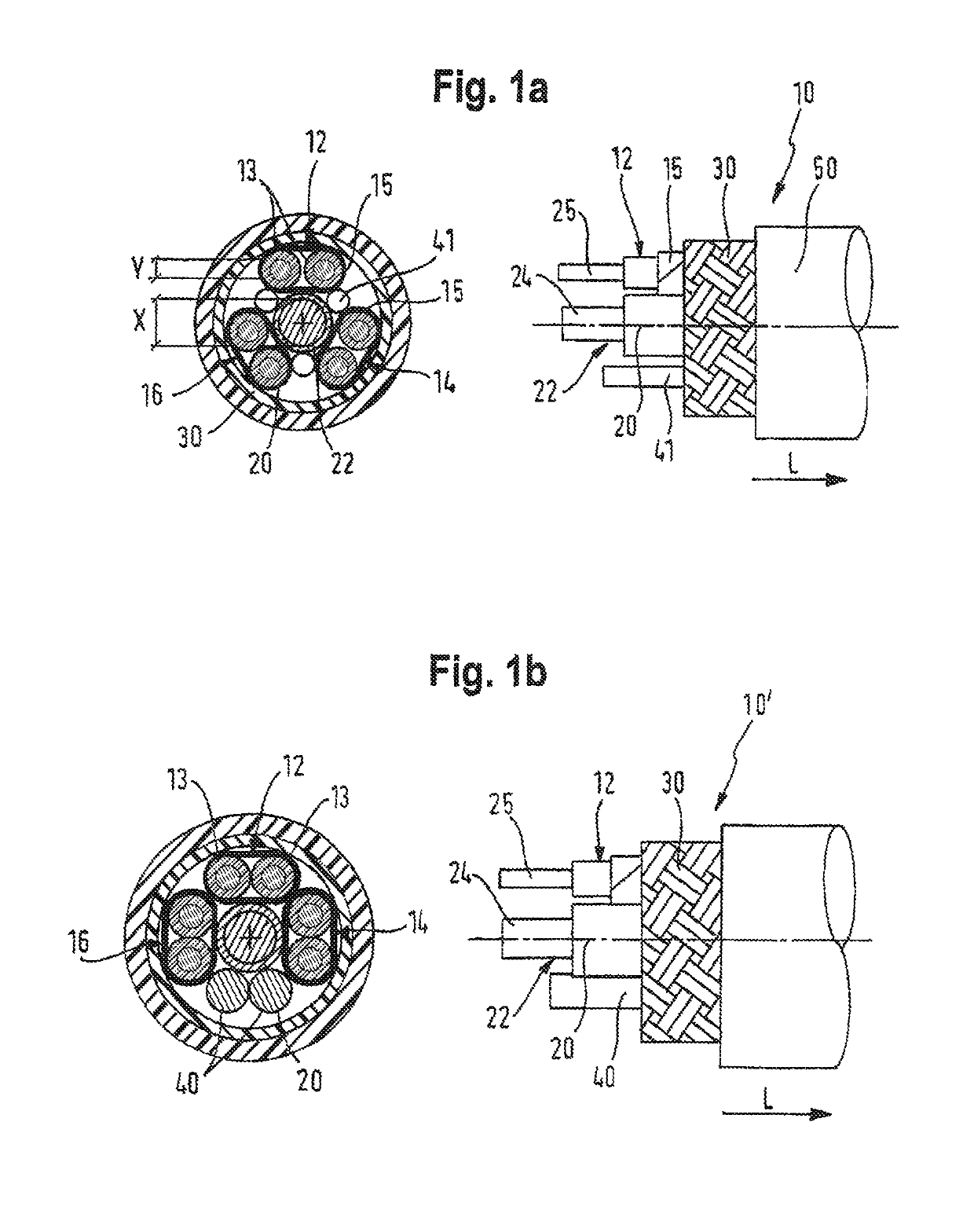
[0054]In FIG. 1a, a cross-sectional view of the present invention is illustrated on the left and a longitudinal view of this embodiment is illustrated, in a partially cut-away side view, on the right. It shows a USB 3.x cable 10 with a total of three wire pairs 12, 14, 16, which are each configured for transmission of a differential data signal. Each wire pair has two adjacent wires 13 running next to one another and is surrounded by a separate shield 15, for example a foil shield.

[0055]The individual wires 13 consist of tinned copper wires, and have a conductor cross section of between 0.05 and 0.2 mm2 and a PP insulation.

[0056]The wire pairs extend in the longitudinal direction L of the cable 10 in a helical arrangement around a common stranding center 20, wherein the stranding center is formed by an additional wire 22 with large conductor diameter X running in the center of the cable. In other words, the wires of the individual wire pairs are not twisted together; rather, the wir...

third embodiment

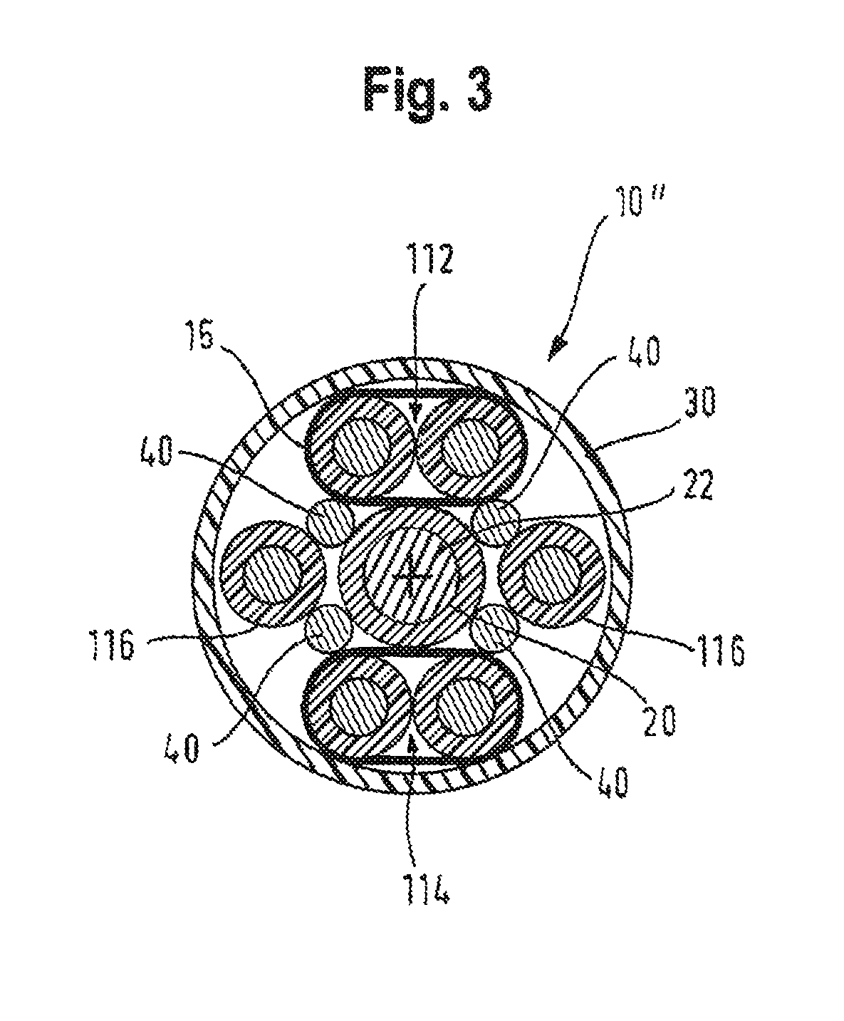
[0065]FIG. 3 illustrates a USB 3.x cable 10″ according to the invention in cross section. This cable 10″ has two wire pairs 112, 114 (the two Super Speed pairs of the USB cable) which are in each case surrounded by a separate foil shield 15 which is in electrical contact with the common shield 30. These two wire pairs 112, 114 are arranged on opposite sides of the central current-carrying wire 22 and extend in a helical arrangement around the common stranding center 20, which is formed by the wire 22. The two wires of a third wire pair 116 (of the High Speed pair D+, D−) are arranged at a distance from one another within the cable, on opposite sides of the central current-carrying wire 22, in each case offset by around 90° relative to the two wire pairs 112, 114. The wires of the third wire pair 116 are also stranded around the stranding center 20 so that, apart from a rotation around the stranding center 20, the cable has the same arrangement of wires in any cross-sectional plane. ...


PUM

PropertyMeasurementUnit
cross-sectional areaaaaaaaaaaa

Abstract

A USB cable having at least two pairs of strands, each pair designed to transmit a differential data signal in the longitudinal direction (L) of the cable, the strands extending helically about a common braiding center such that at least one additional wire pair does not have a separate shield, wherein the wires of the additional wire pair are arranged at a distance from one another on opposite sides of the stranding center.

Description

BACKGROUND OF THE INVENTION[0001]1. Field of the Invention[0002]The invention relates to a cable with at least two wire pairs which are in each case configured for the transmission of a differential data signal. In particular, the invention relates to a USB cable, for example a USB 3.0 cable or a USB 3.1 cable.[0003]2. Description of Related Art[0004]The transmission of USB signals is necessary for an extremely wide range of technical applications. For example, a USB socket may be desired in a rear part of a vehicle in order to allow USB devices to be plugged in, which means that a USB cable needs to be led through the vehicle from the front to the rear. USB sockets or USB connections can also be required in different locations (offices, public institutions, means of transport etc.) for the connection of USB devices, whereby USB cables need to be laid for this purpose.[0005]Conventional USB2 interfaces (for example USB 2.0 interfaces) only have one signal wire pair (D+ and D−) and a...

Claims


Application Information

Patent Timeline
Patent Type & Authority Patents(United States)
IPC IPC(8): H01B7/00H01B11/20H01B11/18H01B11/00H01B11/06
CPCH01B11/002H01B11/20H01B11/1821H01B11/06H01B11/1895
Inventor KUNZ, STEPHANARMBRECHT, GUNNARLODDING, THOMAS
Owner ROSENBERGER HOCHFREQUENZTECHNIK GMBH & CO KG
Why Eureka
Try Eureka