Estrus detection device

a detection device and a technology for detecting ostrus, applied in the field of ostrus detection devices, can solve the problems of significant limiting the usefulness relative of the device, the failure of the device to differentiate between the normal mounting behavior of the mount and the standing mount, and the difficulty in differentiating between the standing heat and the normal mounting behavior, so as to maximize the reproductive performance of the herd and save time and cos

a detection device and a technology for detecting ostrus, applied in the field of ostrus detection devices, can solve the problems of significant limiting the usefulness relative of the device, the failure of the device to differentiate between the normal mounting behavior of the mount and the standing mount, and the difficulty in differentiating between the standing heat and the normal mounting behavior, so as to maximize the reproductive performance of the herd and save time and cos

US20110178423A1Inactive Publication Date: 2011-07-21HATCH IRA STEVEN

Image

  • Estrus detection device
  • Estrus detection device
  • Estrus detection device

Examples


Embodiment Construction

[0034]It is to be understood that both the foregoing general description and the following detailed description are exemplary and explanatory only and are not restrictive of the invention as claimed. The present invention provides a heat detection patch that can detect multiple heats. It is recognized by those skilled in the art that a broad range of patch assemblies may be practiced in accordance with the presently disclosed invention.

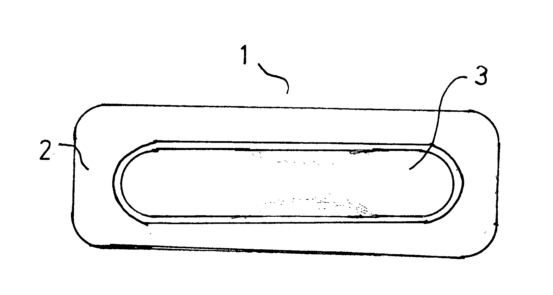
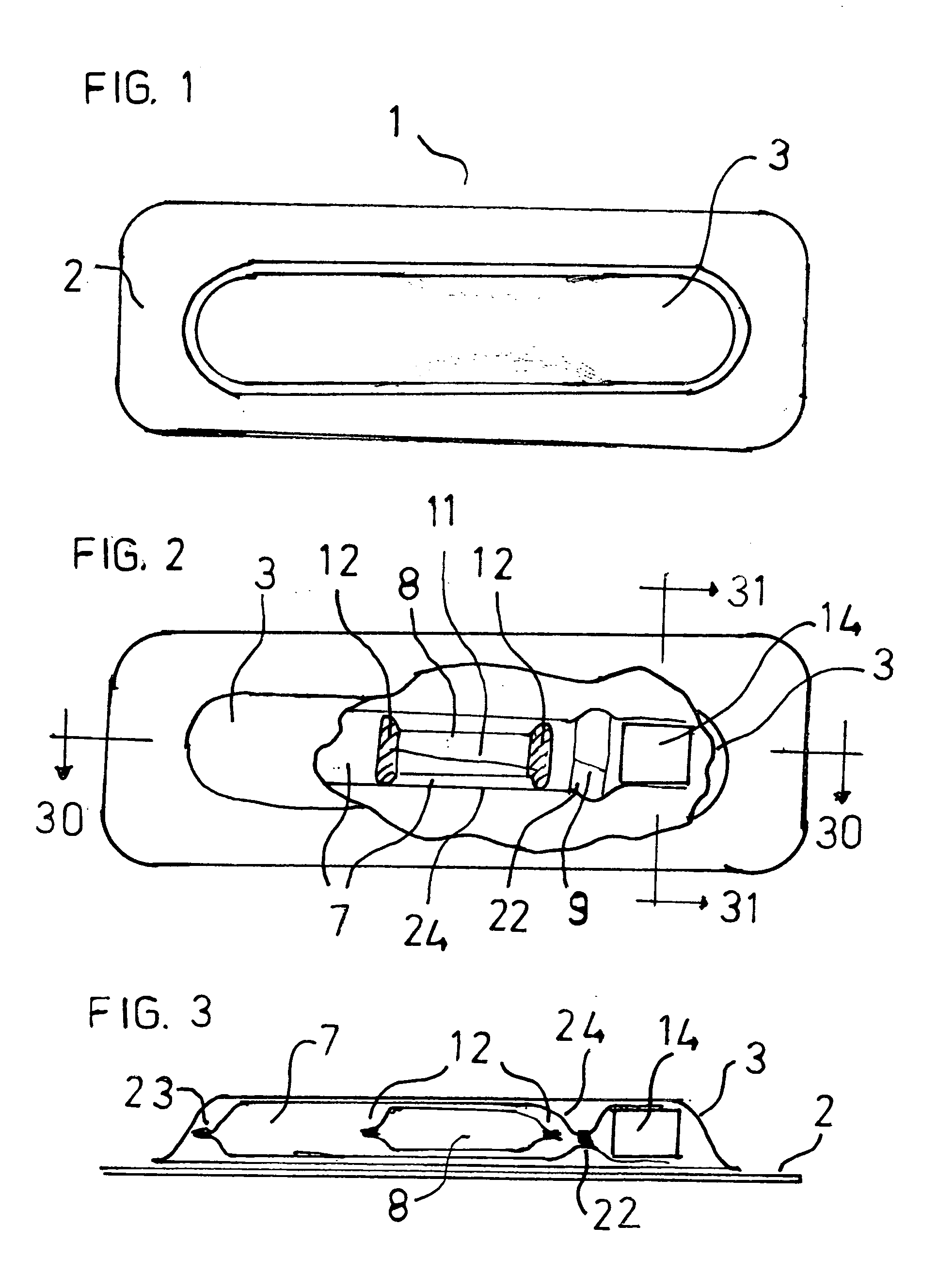
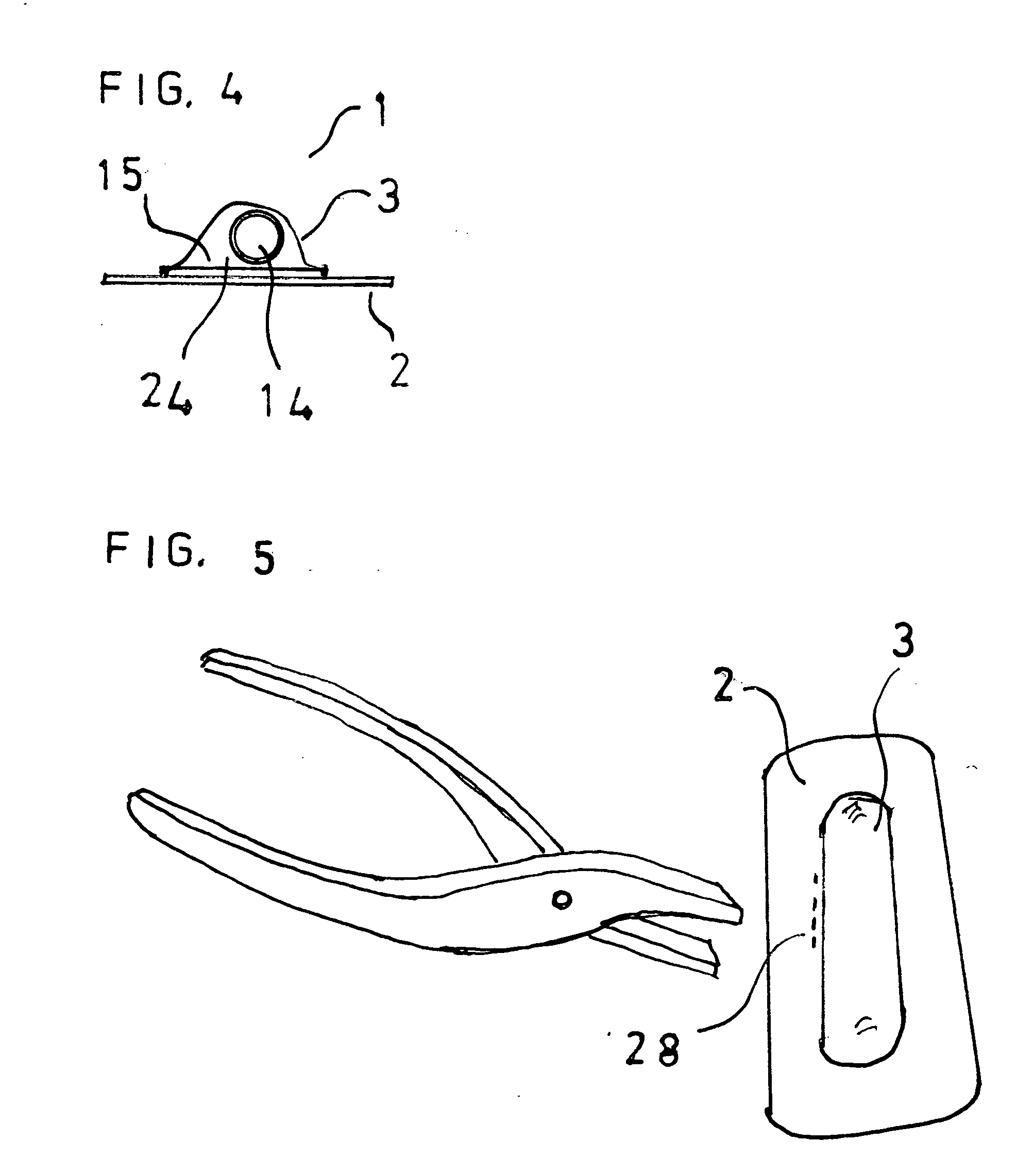
[0035]Referring to FIG. 1, the preferred embodiment of the heat detection patch assembly 1 comprises the animal attachment means 2 that is affixed to the tail head of a cow and a flocked plastic bubble 3 that is attached to animal attachment means 2.

[0036]The partial cross-sectional top view of FIG. 2 shows bubble 3 enclosing first fluid storage reservoir 7 connected to timing chamber 14 by capillary 9, and second fluid storage reservoir 8 contained wholly within first fluid storage reservoir 7. First fluid storage reservoir 7 has a seal end 22 betwee...


PUM


Abstract

Embodiments of the present invention are directed to a device and method for identifying estrus in production animals by detecting one or more standing mounts with a single device.

Description

CROSS REFERENCE TO RELATED APPLICATION[0001]Not applicableSTATEMENT REGARDING FEDERAL SPONSORSHIP[0002]The present invention was not made or developed with Federal sponsorship.FIELD OF THE INVENTION[0003]The present invention relates to an apparatus for detecting standing heats in cows and other animals. The invention further relates to a method for using such an apparatus in animals to detect multiple estruses.BACKGROUND—DESCRIPTION OF PRIOR ART[0004]The artificial insemination of dairy and beef cows is an important means for enhancing productivity through rapid genetic improvement. Artificial insemination of semen from the top industry sires with the most valuable traits can be used much more widely than would be the case if only natural service were available. However, successful insemination programs require herdsmen to accurately determine the timing of estrus so that artificial insemination can lead to conception. In cows, insemination must occur during or shortly after a rela...

Claims


Application Information

Patent Timeline
21 Jul 2011
Publication
US20110178423A1
IPC
A61B10/00
CPC
A61D17/002
Inventors
HATCH, IRA STEVEN