Taking off and landing airplane using variable rotary wings

a variable wing, taking off and landing technology, applied in the direction of rotorcraft, vertical landing/taking off aircraft, vehicles, etc., can solve the problems of loss of human lives, limited maximum speed of a normal vtol, and a lot of difficulties, so as to achieve the effect of ensuring stability

Inactive Publication Date: 2011-07-28
LIM CHAEHO
View PDF4 Cites 47 Cited by
  • Summary
  • Abstract
  • Description
  • Claims
  • Application Information

AI Technical Summary

Benefits of technology

[0005]As mentioned above, the Vertical Take-Off and Land aircraft (VTOL) with variable rotary wings generates lift like a rotary winged aircraft when taking off and moves forward like a helicopter, so it is capable of launching from roads, buildings, parking lots, ship decks, and other flat surfaces; and, when it is necessary to fly at high speeds, it has a jet engine that produces thrust while the pilot adjusts the wing spread then fixes the wings in place using the built-in driving gear with a controlling device. When the aircraft flies at a high speed in this form, if the existing rotary wings are turned by 90°, which transforms the aircraft into a fixed-propeller winged aircraft, the aircraft may drop due to the unstability of the air streams generated around the propellers; thus to remove the problem of increased danger caused by the unsafe conditions, if the aircraft uses the rotary wings when taking off vertically, and the swash plates are tilted forward, thrust will be produced as the vertical lift produced by the rotary wings is redirected to create thrust which will push the aircraft forward at a low speed; and when high speeds are needed, if the air craft uses the jet engine to generate thrust and makes the rotary wings to have the form of spread eagle wings that can produce lift by controlling the servo motor using a controlling device. This is necessary because, if the existing rotary wings that can generate lift and thrust are left in the same position when the aircraft flies at a high speed, the lifts on the two sides of the aircraft may not be balanced and may generate drag since the angles of the rotary wings attached to the farthest ends of both sides of the aircraft may be different so that the rotary wings can add thrust after they are in the fixed-wing position in order to balance the lifts of the fixed rotary wings on both sides of the aircraft; then the risk of dropping due to the sudden loss of speed cause when the rotary wings are turned toward the flying direction may be removed; thus stability can be guaranteed for the VTOL, which has been mainly utilized as military aircraft due to the existing instability. This stability will make it possible to utilize the VTOL as a civil aircraft, and will also allow the craft to fly at super-sonic speeds, which far exceeds the maximum speed of a normal VTOL, which is limited to 500-600 km / h, and thus this invention will have a variety of uses.

Problems solved by technology

Not only in Korea, where a great deal of the area is composed of mountains which poses a lot of trouble in constructing airfields, but also many other countries have insufficient numbers of airfields and the existing airfields are located far away from residential areas due to the great amounts of noise generated by airplanes, so not only have there been a lot of difficulties for small-to-medium sized groups or individuals in attempting to depart from places in the vicinity of their houses or work places and directly move to the desired destinations using airplanes without wasting precious time and energy; or for people in attempting to go into dangerous areas; or for military corps in attempting to move fast to locations for operations and vertically take off or land in order to execute operations, but also there have been a lot of problems involving accidents and the loss of human lives created by the existing VTOL airplanes due to their lack of safety caused by the unstability of the air current created when their rotary wings have been turned 90° anteriorly.
Also, since the maximum speed of a normal VTOL is limited to 500-600 km / h under current technologies.
Flight speed is very important to people who need to reach their destination quickly, such as businessmen with deadlines or people who are exhausted by long flights, but many difficulties and problems occur when attempting to obtain higher speeds.

Method used


Image

  • Taking off and landing airplane using variable rotary wings
  • Taking off and landing airplane using variable rotary wings
  • Taking off and landing airplane using variable rotary wings

Examples


Embodiment Construction

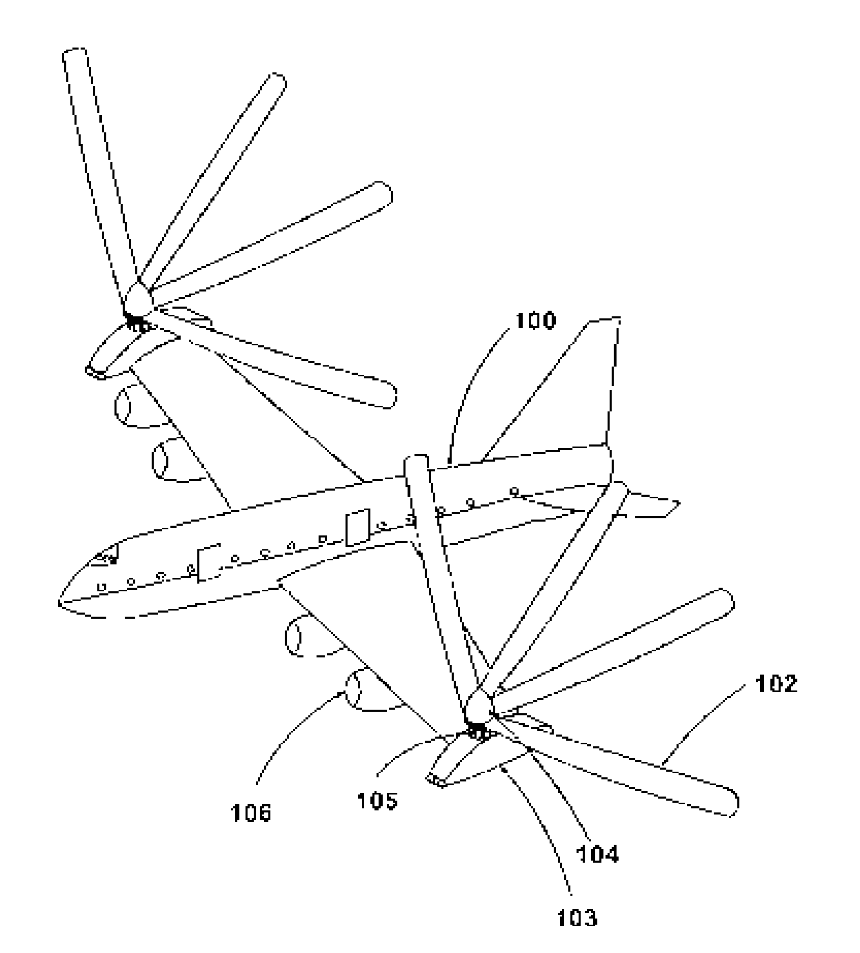
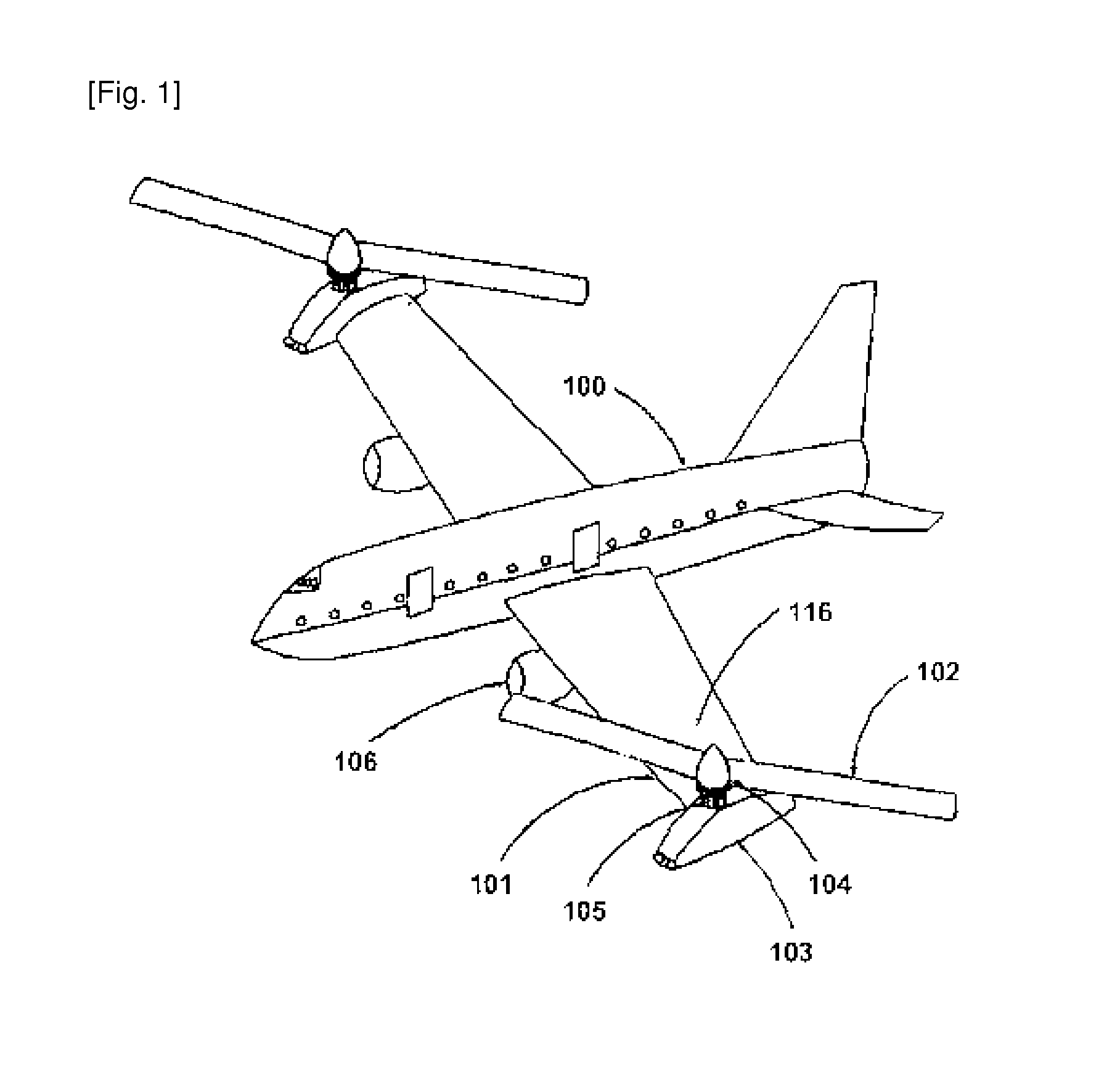
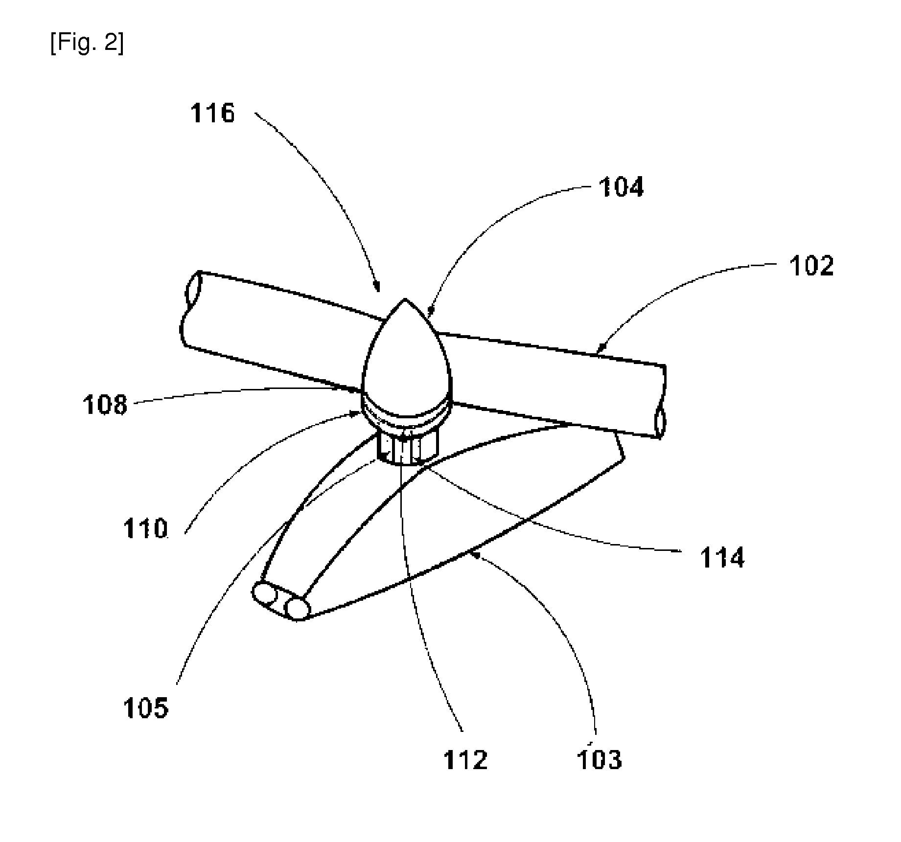
[0023]As illustrated in the figures, the entire composition of this invention is comprised of a flying body (100), the flying wings (101) mounted unmovably on the sides of the body (100), the rotary wings (102) which are rotated by the rotary wing engines (103) mounted on the sides of the above mentioned flying wings (101) and the rotary wing angle adjusting means (104) mounted on the center of the rotary wings (102).

[0024]The VTOL (100) rotates the rotary wings (102) to generate lift when taking-off; and when going forward, the lower swash plate (110) is tilted toward the front of the VTOL (100) by the hinge type rod (114) connected to the control device in the operating seat making the upper swash plate (108) connected with the lower swash plate (110) through the ball bearing (112) rotate in the tilted state and making the rotary wing angle adjusting means (104) mounted on the upper swash plate (108) rotate together in the tilted state and consequently the angle of attack of the w...


PUM


Abstract

This invention is regarding a VTOL aircraft that is designed to enable it to take off by generating lift through rotary wings like a helicopter and then moving forward; and when it flies at high speeds, it is able to use jet engines so that it can generate lift through fixed wings while the rotary wings are transformed into fixed wings to generate lift by adjusting the angles between the individual wings thereby enhancing the efficiency.

Description

TECHNICAL FIELD[0001]This invention is regarding a VTOL aircraft using variable rotary wings that would take off vertically by generating lift using the rotary wings; fly forward at high speeds with the thrust generated using jet engines while adjusting the angles between each of the rotary wings to make them into a form of fixed wings that can efficiently generate liftBACKGROUND ART[0002]Not only in Korea, where a great deal of the area is composed of mountains which poses a lot of trouble in constructing airfields, but also many other countries have insufficient numbers of airfields and the existing airfields are located far away from residential areas due to the great amounts of noise generated by airplanes, so not only have there been a lot of difficulties for small-to-medium sized groups or individuals in attempting to depart from places in the vicinity of their houses or work places and directly move to the desired destinations using airplanes without wasting precious time and...

Claims


Application Information

Patent Timeline
Patent Type & Authority Applications(United States)
IPC IPC(8): B64C27/22B64C29/00
CPCB64C29/0025B64C27/24
Inventor LIM, CHAEHO
Owner LIM CHAEHO
Why Eureka
Try Eureka