Device for supplying a fluid for explosion forming

a technology of explosive forming and fluid feed, which is applied in the direction of valves, mechanical devices, transportation and packaging, etc., can solve the problems of imposing high requirements on the tightness of the valve, and achieve the effects of reducing the movement possibility facilitating the production of the valve element, and increasing the stability of the valve elemen

Active Publication Date: 2011-07-28
COSMA ENG EURO AG
View PDF52 Cites 0 Cited by
  • Summary
  • Abstract
  • Description
  • Claims
  • Application Information

AI Technical Summary

Benefits of technology

[0022]Advantageously, a valve element can have a middle piece, having a valve head, and an edge area, in which the axial position of the middle piece relative to the edge area can be adjusted by adjustment means. The axial position, and therefore the closure position of the valve head, can therefore be properly adjusted.
[0023]Alternatively, the valve element can be designed integrally, i.e. in one piece. This increases the stability of the valve element and simplifies its production.
[0024]In one variant of the invention, the valve element can have a shoulder that is moveable in a movement space in the valve housing that limits the axial movement of the valve element. The movement possibility of the valve element is thus limited with tec

Problems solved by technology

In this process, large forces act on the valve, which aga

Method used


Image

  • Device for supplying a fluid for explosion forming
  • Device for supplying a fluid for explosion forming
  • Device for supplying a fluid for explosion forming

Examples


second embodiment

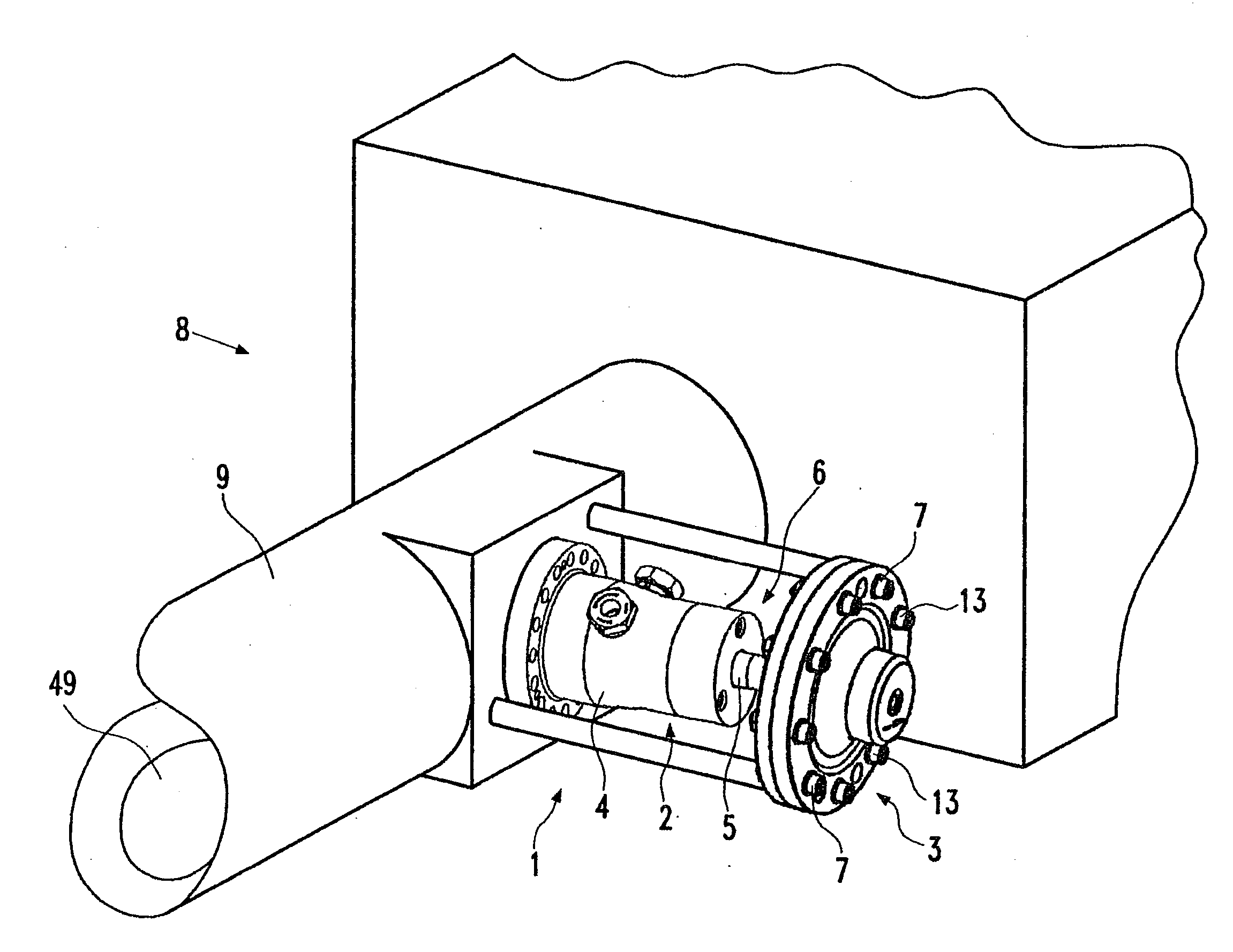
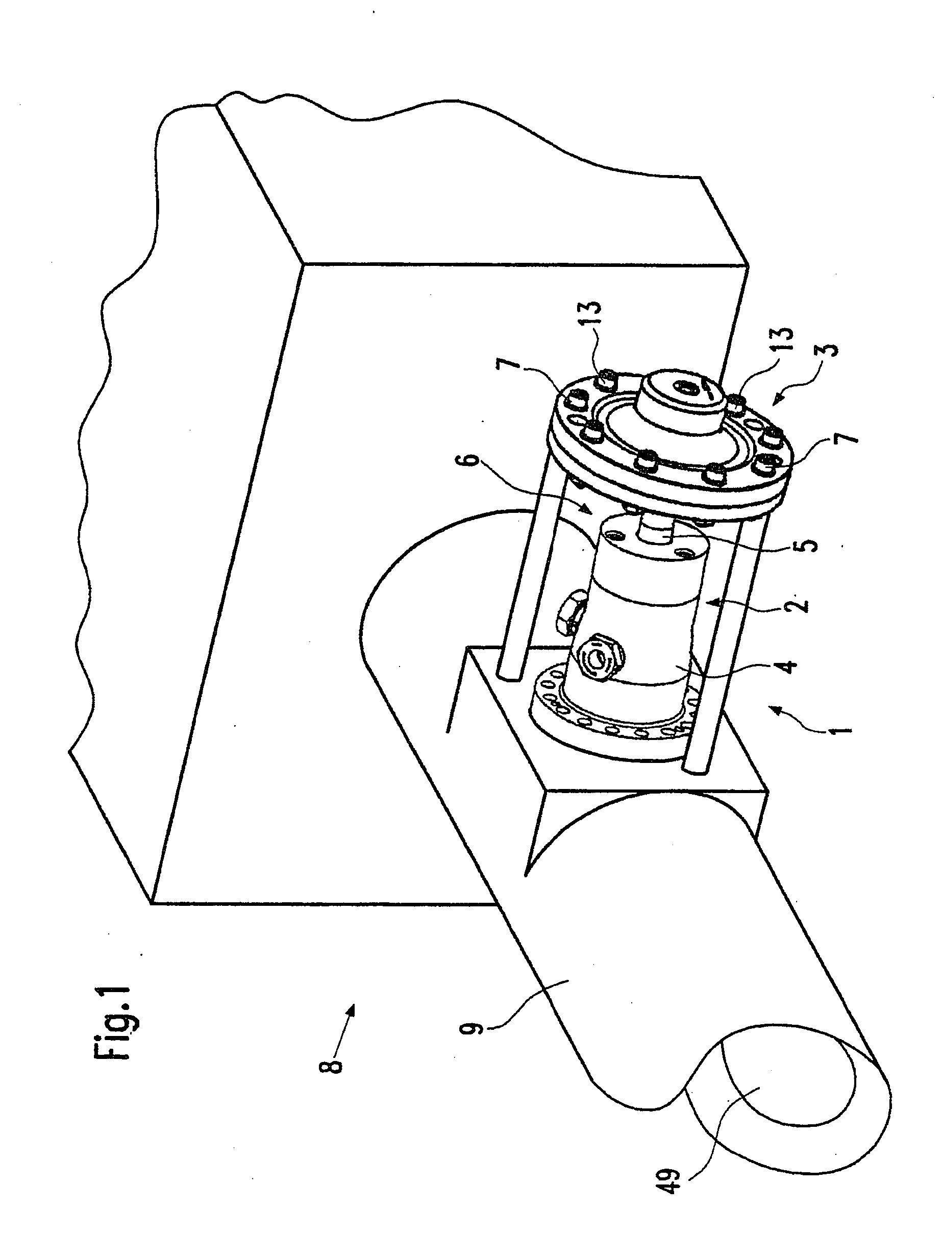
[0069]FIGS. 4 to 7 show the device 1 according to the invention for fluid feed for explosive forming.

[0070]The design of the second embodiment is similar to that of the first embodiment. Only the differences in the two embodiments are therefore outlined below. If the same components or components equivalent in function are involved in FIGS. 4 to 8 of the second embodiment, the same reference numbers as in FIGS. 1 to 3 of the first embodiment are used, so that the description of FIGS. 1 to 3 is referred to in this respect.

[0071]In FIGS. 4 to 7, the activating mechanism 3 was left out for reasons of clarity. It is arranged in this embodiment similarly to the first embodiment behind valve 2 of device 1, as shown, for example, in FIG. 2 of the first embodiment. As an alternative to the design operated with a fluid, as depicted in the first embodiment, the activating mechanism 3 can also be operated electrically. In the electrically operated design, an electromagnet that interacts with a...

first embodiment

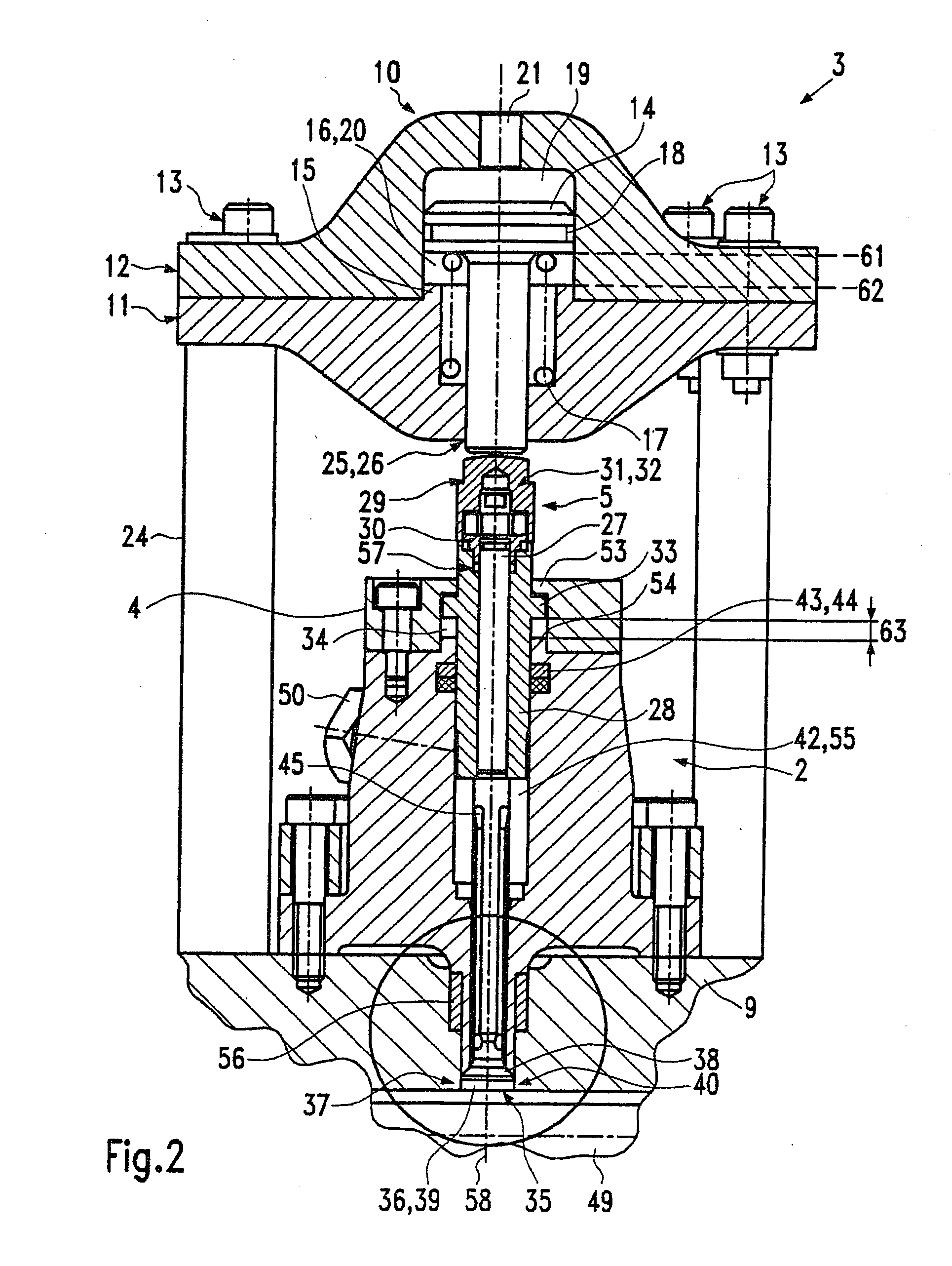
[0076]Here again, the valve housing 4 is in several parts, similar to the It has individual segments 4a to 4f. Seals 64 that seal the individual segments 4b to 4e relative to each other are provided between the individual segments 4b to 4e of the valve housing. In this embodiment, individual segments 4c to 4e in the valve housing 4 are also sealed relative to valve element 5. The segments 4b to 4e are sealed relative to valve element 5 by sealing means 43, and the valve segment 4a is sealed relative to valve element 5 by means of valve seat 37. This increases the safety against leakage. In other embodiments of the invention, however, correspondingly fewer seals 43 can be provided. Each individual element 4a to 4e need not necessarily be sealed relevant to valve element 5.

[0077]The pressure chamber 42, through which the valve element 5 extends, is formed in the valve housing 4 in this second embodiment. This means, in contrast to the first embodiment, it is only formed by non-moving...


PUM

PropertyMeasurementUnit
Lengthaaaaaaaaaa
Pressureaaaaaaaaaa
Elasticityaaaaaaaaaa

Abstract

With the invention, a device for fluid feed for explosive forming, which has a valve and an activating mechanism to activate the valve, is to be improved, so that the device permits both good filling of a die with fluid and good sealing during the explosive forming process in a technically simple design. This task is solved by a device for fluid feed for explosive forming that has a valve and an activating mechanism to activate the valve, in which the activating mechanism is arranged separate from the valve in an inactivated valve state.

Description

CROSS-REFERENCE TO RELATED APPLICATIONS [0001]This application is a National Entry Application of PCT / EP08 / 004375, filed Jun. 2, 2008, which claims priority from German Patent Application Serial No. 102007036196.5, filed on Aug. 02, 2007, entitled “ Vorrichtung für die Zufuhr eines Fluids für Explosionsumformen” (Device For Supplying A Fluid For Explosion Forming), the disclosure of which is incorporated herein by reference for all purposes.FIELD OF THE INVENTION [0002]The invention concerns a device for fluid feed for explosive forming with the features of the preamble of claim 1.BACKGROUND OF THE INVENTION[0003]Such devices generally include a valve, via which admission of an explosive gas into an element of the explosive forming die that accommodates the valve is controlled. By igniting the explosive gas in the explosive forming die, a detonation front is formed that propagates along the die. In this process, large forces act on the valve, which again impose high requirements on ...

Claims


Application Information

Patent Timeline
IPC IPC(8): F16K31/12F16K31/02
CPCB21D26/08Y10S72/706F16K31/0655Y10T137/7668
Inventor STRANZ, ANDREASZAK, ALEXANDER
Owner COSMA ENG EURO AG
Why Eureka
Try Eureka