Mining machine with driven disc cutters

a disc cutter and disc cutter technology, applied in cutting machines, cutting machines, cutting tools, etc., can solve the problems of supporting weight and tensile fracture of rocks, and achieve the effect of effectively using an eccentric drive disc cutter to min

Active Publication Date: 2011-07-28
JOY GLOBAL UNDERGROUND MINING LLC
View PDF18 Cites 24 Cited by
  • Summary
  • Abstract
  • Description
  • Claims
  • Application Information

AI Technical Summary

Benefits of technology

[0006]It is an object of the disclosure to provide a mining machine...

Problems solved by technology

Because the device usually applies a load at an angle to the rock face, it causes tensile fracture of the rock, instead of crushing the rock.
One difficulty when using such ...

Method used


Image

  • Mining machine with driven disc cutters
  • Mining machine with driven disc cutters
  • Mining machine with driven disc cutters

Examples


Embodiment Construction

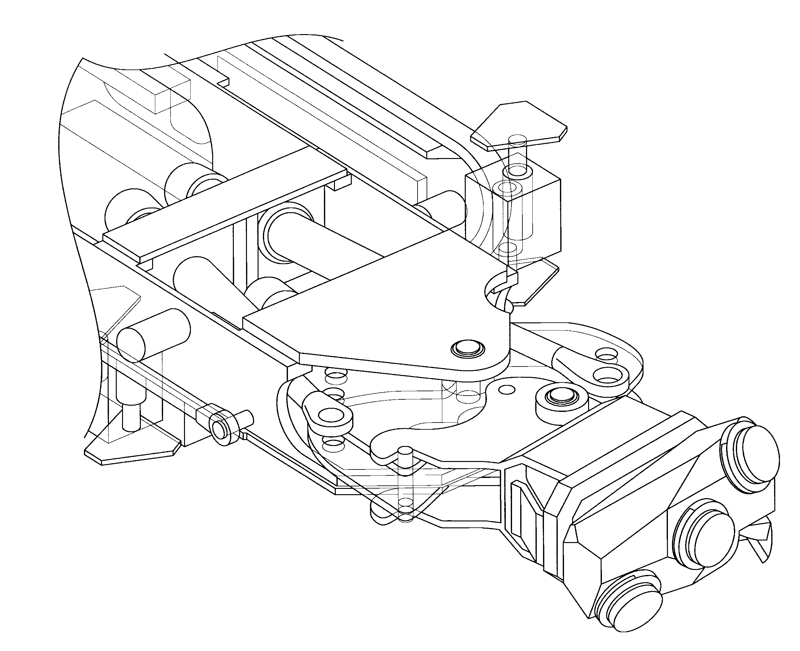
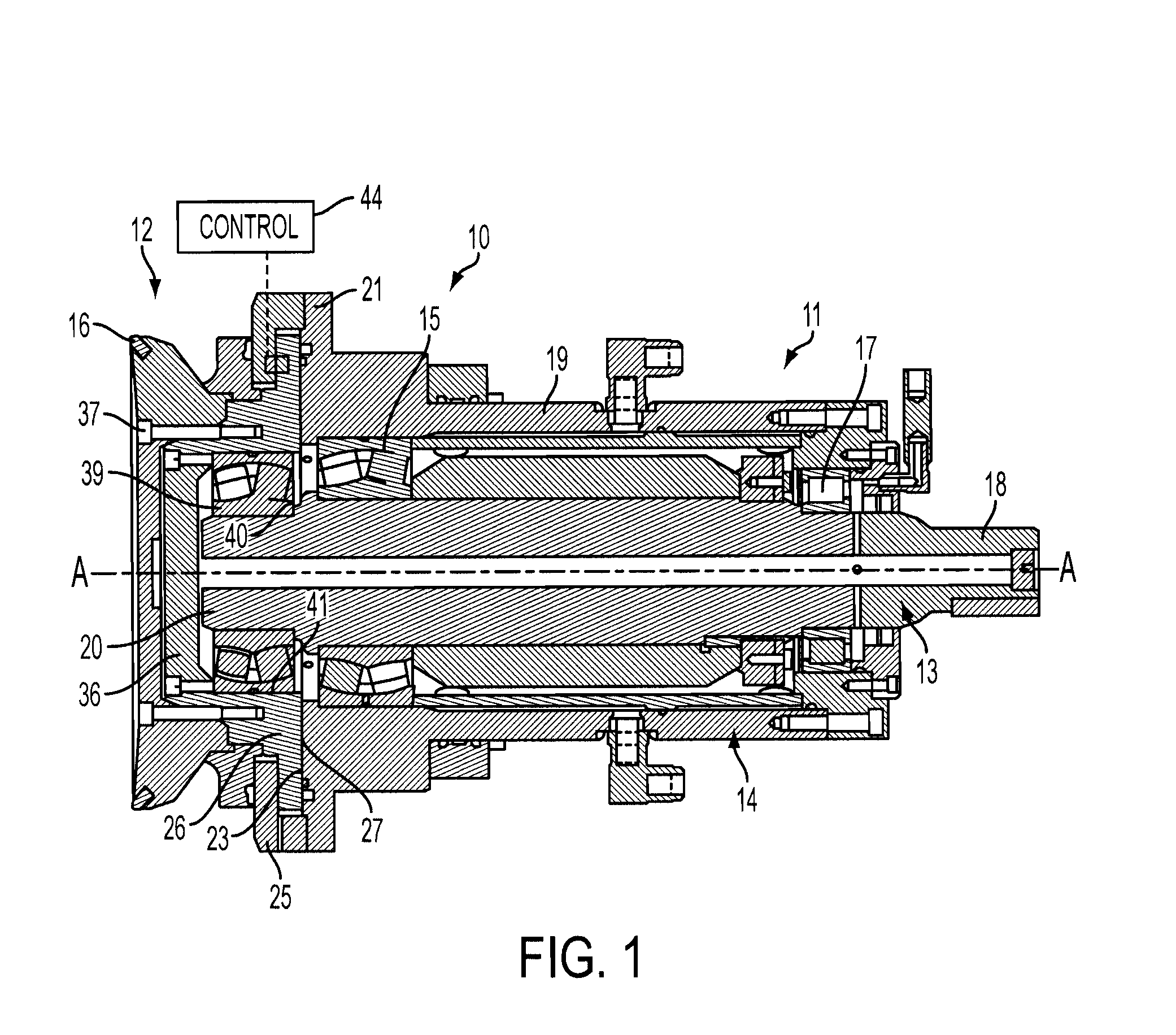
[0022]FIG. 1 is a cross-sectional view of a disc cutter assembly. The disc cutter assembly 10 includes a mounting assembly 11 and a rotary disc cutter 12. The mounting assembly 11 includes a mounting shaft 13 which is rotatably mounted within a housing 14, that can constitute or be connected to a large mass for impact absorption. The housing 14 thus, can be formed of heavy metal or can be connected to a heavy metallic mass. The mounting shaft includes a shaft drive section 18 and a disc drive section 20.

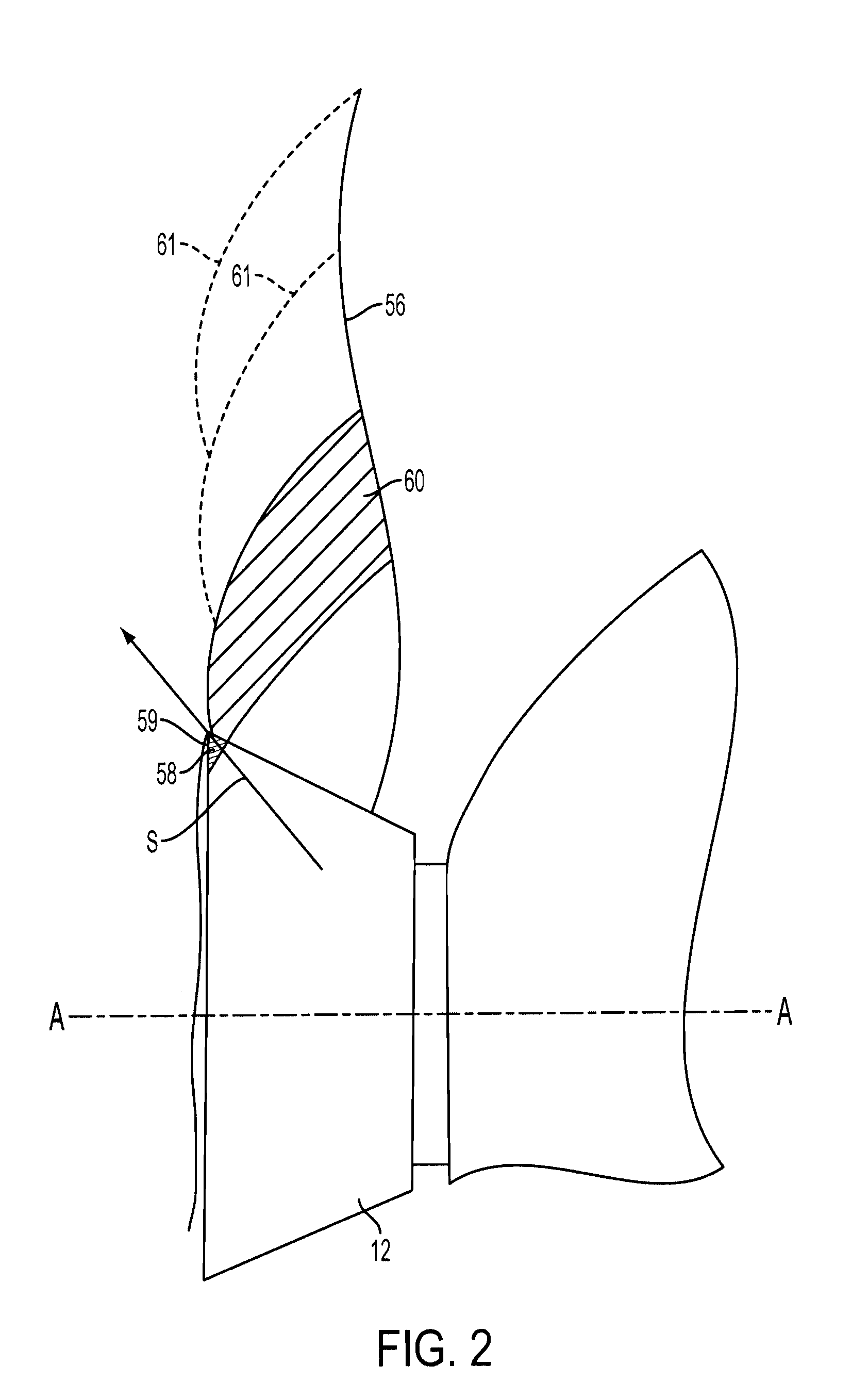
[0023]A rock excavating or mining machine according to the present invention includes the disc cutter 12, and is characterized in that the disc cutter is driven to move in an eccentric manner. The magnitude of eccentric movement is directly proportional to the amount of offset between the disc drive section axis and the center of the shaft drive section axis and generally that amount is relatively small. Preferably, the disc cutter 12 is caused to be driven eccentrically through a re...


PUM


Abstract

A mining machine including a cutting mechanism comprising an arm having an arm end, a disc cutter adapted to engage the material to be mined and mounted on the arm end. The disc cutter is driven by the arm into the material to be mined, and the arm further includes a main portion, and a wrist portion pivotally attached to the main portion.

Description

BACKGROUND OF THE INVENTION[0001]The present invention relates to a mining machine and is particularly, although not exclusively, concerned with excavating hard rock.[0002]Sugden U.S. Pat. No. 6,561,590 issued May 13, 2003, describes a cutting device is utilized in the herein later described invention. The Sugden device is a cutting device of a rotary (disc) undercutting type, that provides improved rock removal from a rock face and which is relatively economical to manufacture and operate.[0003]The Sugden device employs a reaction mass of sufficient magnitude to absorb the forces applied to the rock by the disc cutter during each cycle of oscillation, with minimum or minor displacement of the device, or the structure supporting the device. Because the device usually applies a load at an angle to the rock face, it causes tensile fracture of the rock, instead of crushing the rock. This tensile fracture force applied to the rock is substantially less than that needed with crushing for...

Claims


Application Information

Patent Timeline
IPC IPC(8): E21C25/16
CPCE21C25/16E21C31/04
Inventor SKEA, THEUNIS F.
Owner JOY GLOBAL UNDERGROUND MINING LLC
Why Eureka
Try Eureka