

Electro-optic display and related driving method thereof
- Summary
- Abstract
- Description
- Claims
- Application Information
AI Technical Summary
Benefits of technology
Problems solved by technology
Method used
Image

Examples
Embodiment Construction
[0026]Traditionally, for example, in an LCD display, when a user reads a book or browses a web on an electro-phoretic display, the whole frame of the display needs to be updated if the user changes to another page or changes to another website. Because the LCD display has to update all pixels of the frame, that will consume much unnecessary power.
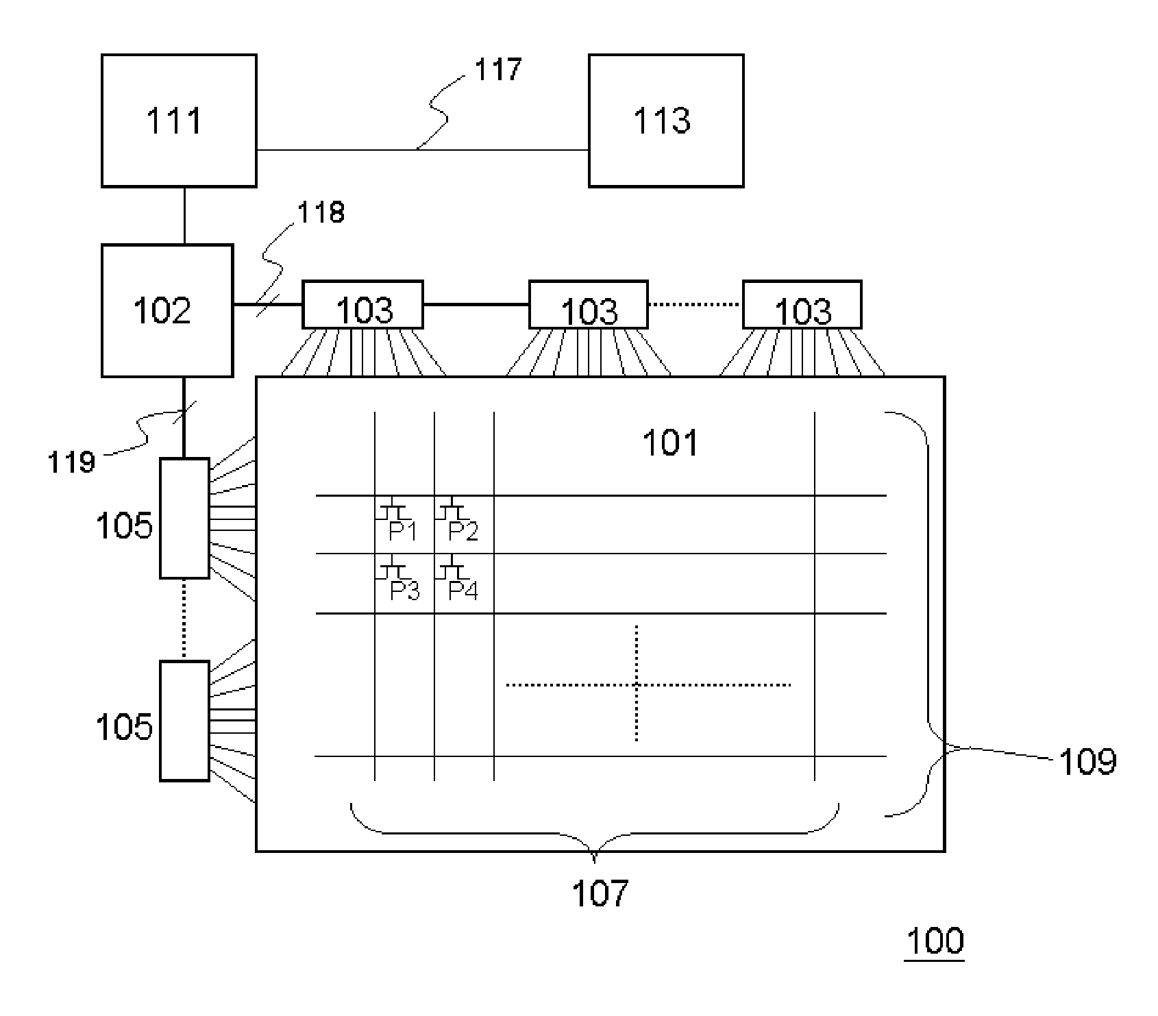
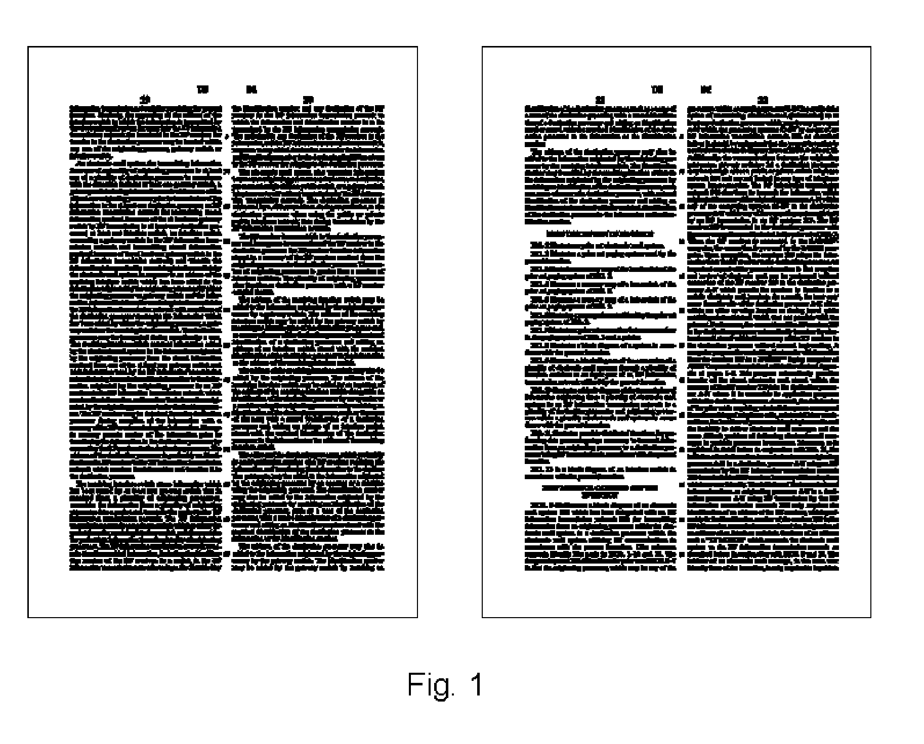
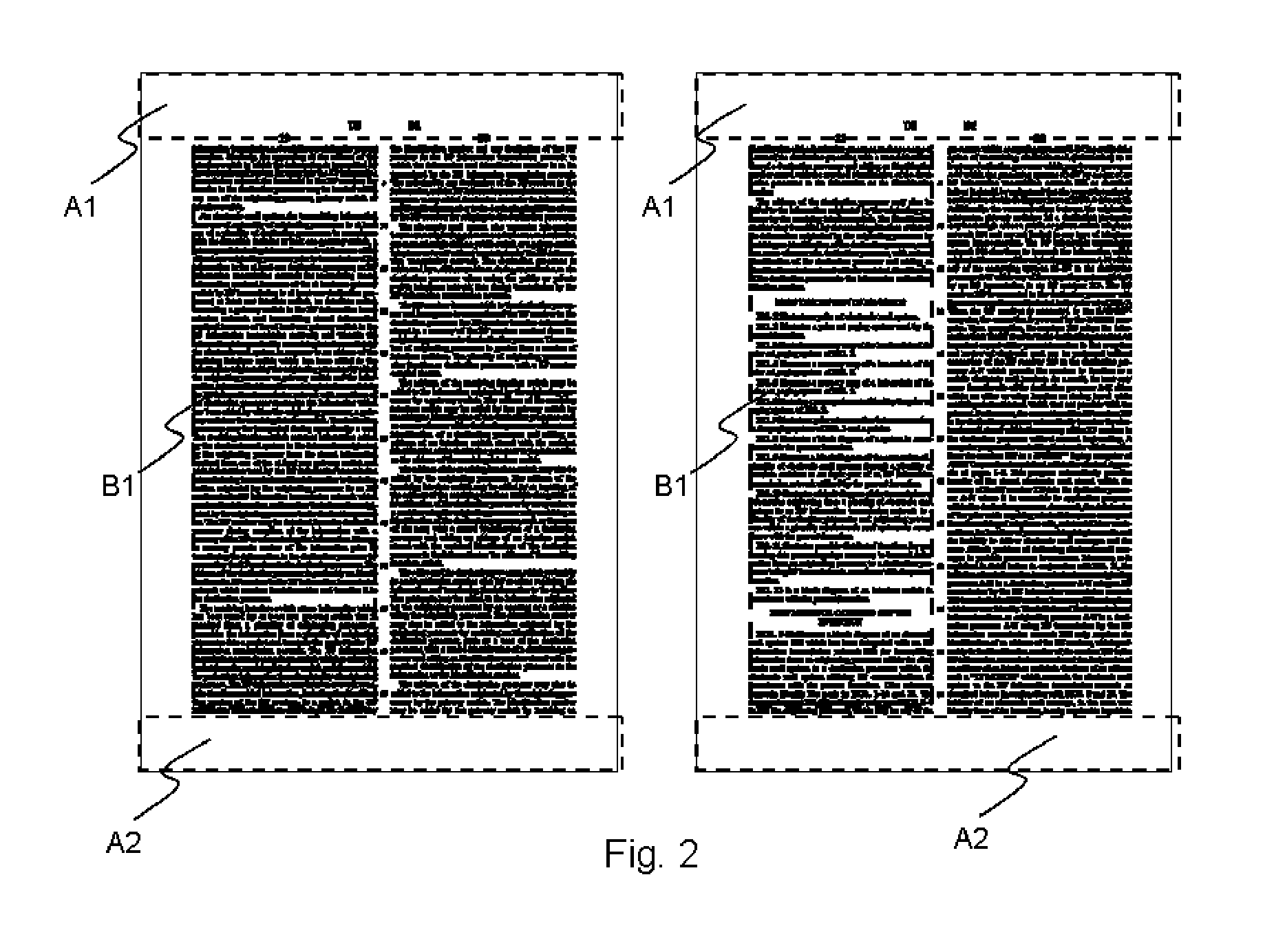
[0027]Therefore, the present invention provides a novel electro-phoretic display and related driving method for updating pixels when the frame changes. Please refer to FIG. 1, which shows two different pages of an article. When a user changes page between these two pages, some areas of these two pages are holding unchanged. In general, a page of a book may have upper region, lower region, left region and right region; these regions are kept white with only page number and chapter title on the lower region and the upper region. The central region is the text region or figure region, and normally it has its fix dimension and position especial...
PUM
 Abstract
Description
Claims
Application Information