Projection apparatus and image blur preventive control method for projection apparatus

a technology of projection apparatus and preventive control method, which is applied in the direction of static indicating device, printing, instruments, etc., can solve the problems of large vibration given to the main body of the apparatus, easy to affect the projection apparatus, and easy to make an observer uncomfortable, so as to prevent the blurring of the image and reduce the cost

Inactive Publication Date: 2011-07-28
SEIKO EPSON CORP
View PDF5 Cites 11 Cited by
  • Summary
  • Abstract
  • Description
  • Claims
  • Application Information

AI Technical Summary

Benefits of technology

[0006]An advantage of some aspects of the invention is to provide a projection apparatus and an image blur preventive control method for the projection apparatus capable of effectively preventing image blur caused by vibration of the main body of the projection apparatus.

Problems solved by technology

In fact, however, vibration given to the main body of the apparatus has a large effect even on the fixed installation, and image blur caused by the vibration makes an observer uncomfortable.
Particularly, in case of the suspension type, the projection apparatus is easily affected by vibration of the ceiling or the wall.
This necessity greatly increases the cost.
Accordingly, even when construction for installation requiring high cost is completed, image blur caused by vibration cannot be perfectly prevented.

Method used


Image

  • Projection apparatus and image blur preventive control method for projection apparatus
  • Projection apparatus and image blur preventive control method for projection apparatus
  • Projection apparatus and image blur preventive control method for projection apparatus

Examples


first embodiment

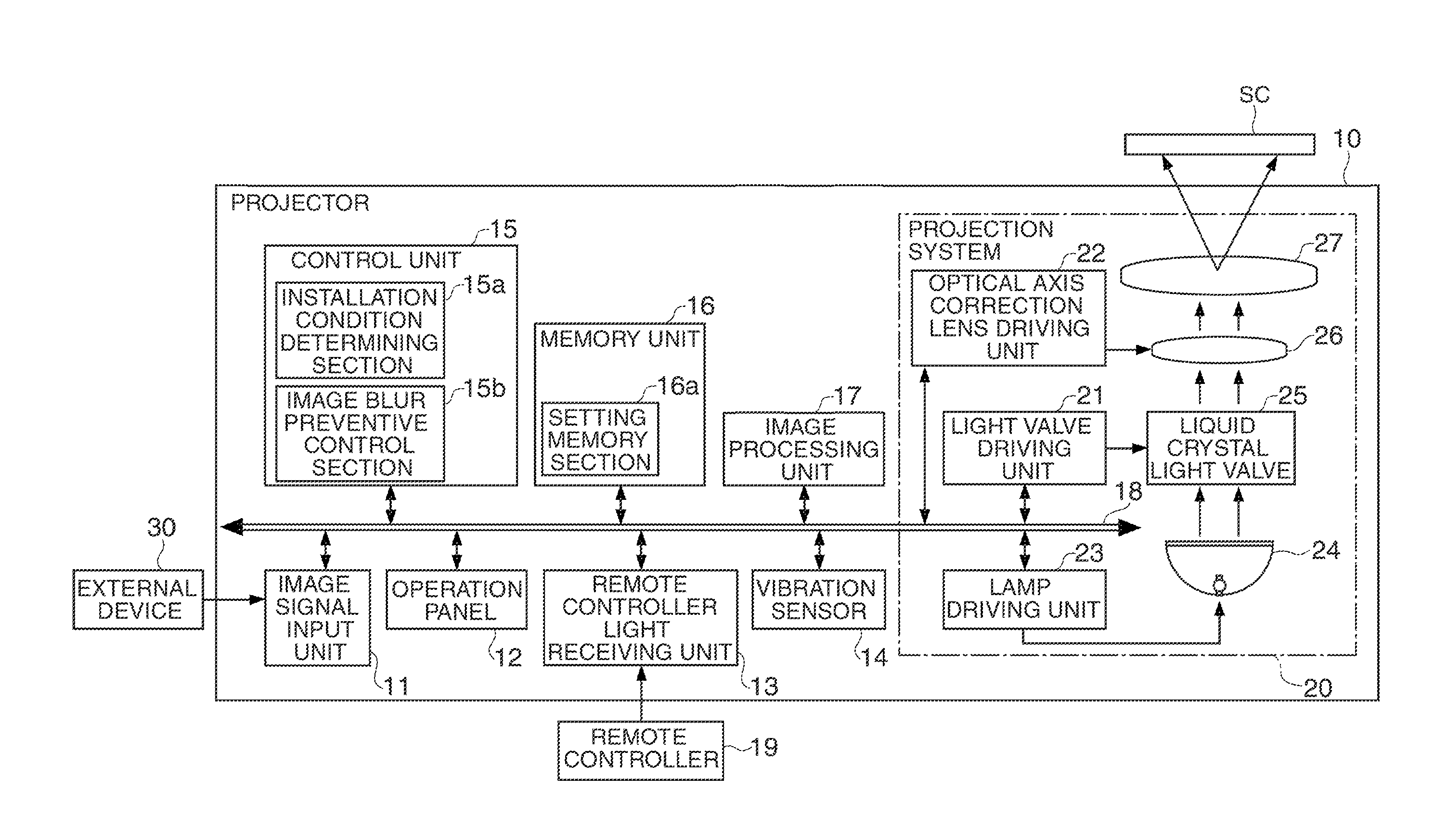
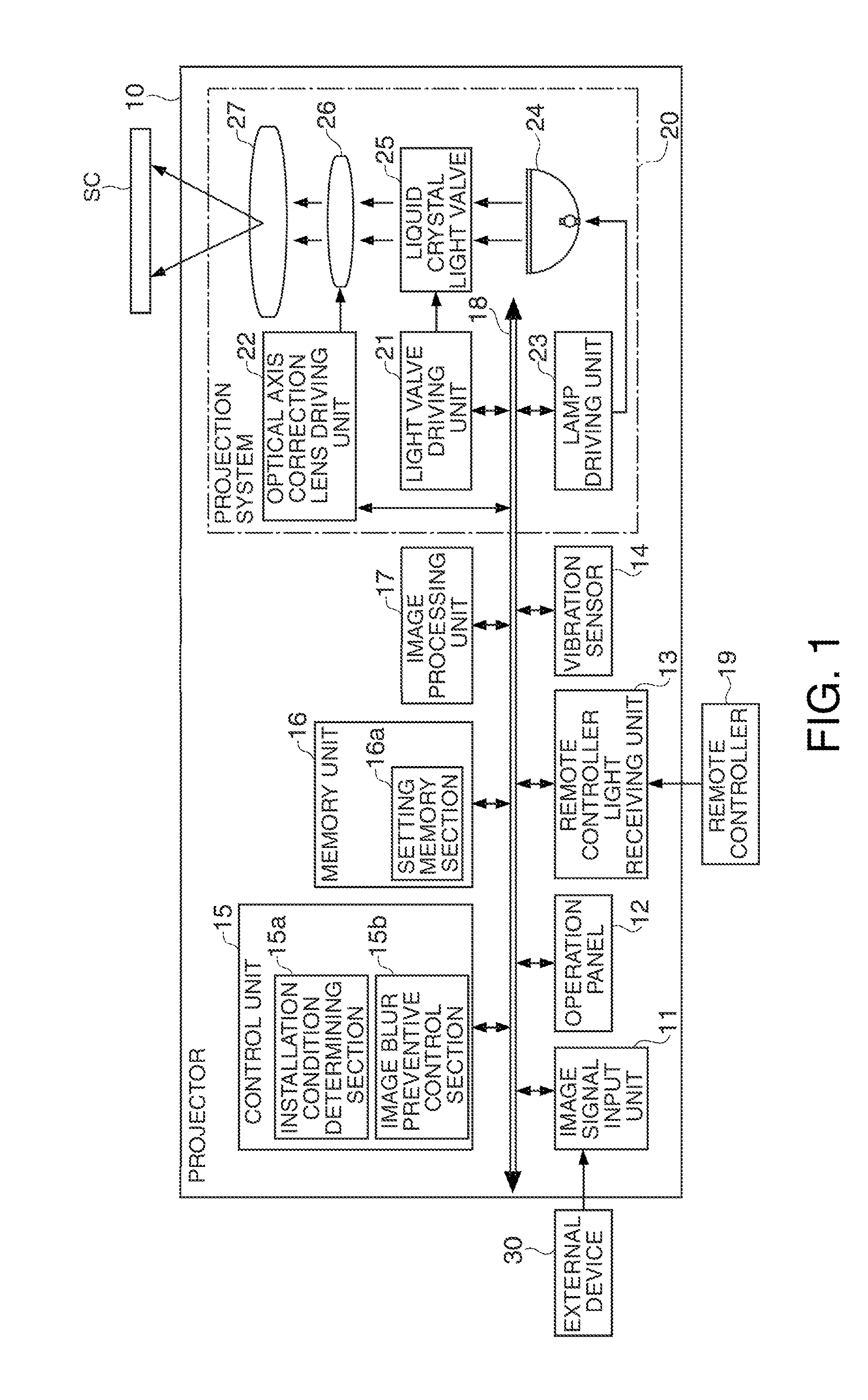
[0032]A projection apparatus (projector 10) and an image blur preventive control method for the projection apparatus according to a first embodiment of the invention are hereinafter described with reference to the drawings. FIG. 1 is a block diagram showing the structure of the projector 10. As shown in the figure, the projector 10 includes an image signal input unit 11, an operation panel 12, a remote controller light receiving unit 13, a vibration sensor 14 (vibration detecting unit), a control unit 15, a memory unit 16, an image processing unit 17, a bus line 18, and a projection system 20.

[0033]The image signal input unit 11 has a plurality of image input terminals to which various types of image signals are inputted from an external device 30 such as a personal computer and a video player. The operation panel 12 is provided on the main body of the projector 10, and has a group of buttons operated for performing various operations. The group of buttons include a menu button for ...

second embodiment

[0054]A second embodiment is now described with reference to FIG. 5. This embodiment is different from the first embodiment in that the image blur preventive control is performed not for the projection systems 20 and 50 as in the first embodiment but for the image processing unit 17. In the following explanation, only the parts different from the corresponding parts in the first embodiment are discussed. In the second embodiment, the same reference numbers are given to components same as those in the first embodiment, and the same detailed explanation is not repeated. Modified examples applied to the structures in the first embodiment are similarly applied to the corresponding structures in the second embodiment.

[0055]FIG. 5 is a block diagram showing the structure of the projector 10 according to the second embodiment. The projector 10 in this embodiment is different from that in the first embodiment in that the optical axis correction lens driving unit 22 and the optical axis corr...


PUM


Abstract

A projection apparatus includes: a projection system which projects an image; a vibration detecting unit which detects vibration given to the main body of the apparatus; an installation condition determining unit which determines the installation condition of the main body of the apparatus; and an image blur preventive control unit which performs image blur preventive control for preventing blurring of the image caused by the vibration detected by the vibration detecting unit based on the vibration, wherein the image blur preventive control unit performs the image blur preventive control in accordance with the installation condition determined by the installation condition determining unit.

Description

BACKGROUND[0001]1. Technical Field[0002]The present invention relates to a projection apparatus which projects images toward a screen and an image blur preventive control method for the projection apparatus.[0003]2. Related Art[0004]A projection apparatus (projector) of a type which detects blurring of an image caused by vibration of hand and corrects the image in accordance with the amount of the blur is known (for example, see WO2005 / 083507). The projection apparatus having this structure prevents blurring of a projection image (image blur) caused by vibration of hand while the projection apparatus held by hand is projecting the image.[0005]A typical projection apparatus is not a type held by hand as described above but a type fixed for installation. The fixed installation type includes a normal installation type disposed on a desk or the like, and a suspension type suspended from above such as a type suspended from a ceiling or a wall. In case of the fixed installation, it genera...

Claims


Application Information

Patent Timeline
Patent Type & Authority Applications(United States)
IPC IPC(8): G09G5/02G02B27/64
CPCG02B27/646G03B5/02G03B21/14G03B2217/005H04N9/3185H04N9/3194H04N9/3197G03B2205/0007G03B21/145
Inventor FUKAZAWA, OSAMU
Owner SEIKO EPSON CORP
Why Eureka
Try Eureka