Image forming apparatus

a technology of image forming and forming tubes, which is applied in the direction of electrographic process apparatus, instruments, optics, etc., can solve the problems of reducing image quality, complicated resultant apparatus, and inconvenient operation,

Inactive Publication Date: 2011-07-28
CANON KK
View PDF15 Cites 26 Cited by
  • Summary
  • Abstract
  • Description
  • Claims
  • Application Information

AI Technical Summary

Benefits of technology

[0014]control means for determining the order of formation of the toner image with the color toner and the toner

Problems solved by technology

However, in an electrophotographic type, the glossiness of an output image is not uniform in many cases.
Therefore, the entire image has non-uniform glossiness, so that an image quality is lowered.
However, in this case, there arises a problem such that a new manufacturing line is needed or a resultant apparatus is complicated.
However, there is a need to subject the image to the fixation twice,

Method used


Image

  • Image forming apparatus
  • Image forming apparatus
  • Image forming apparatus

Examples


embodiment 1

(1) Image Forming Portion

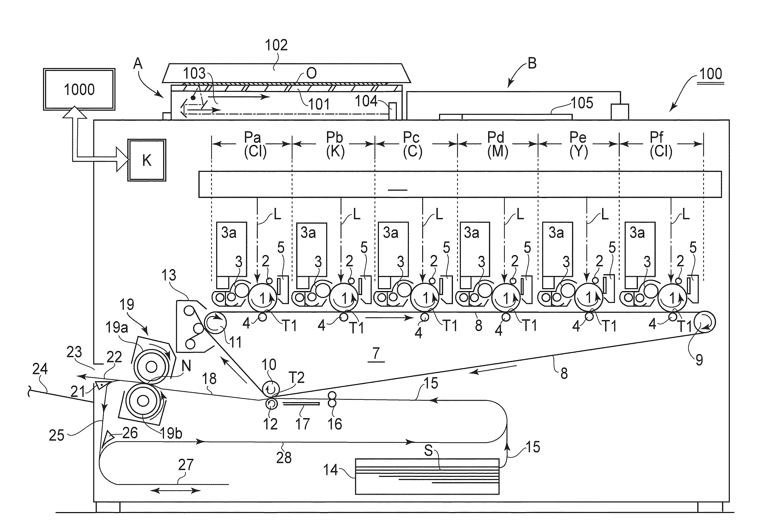
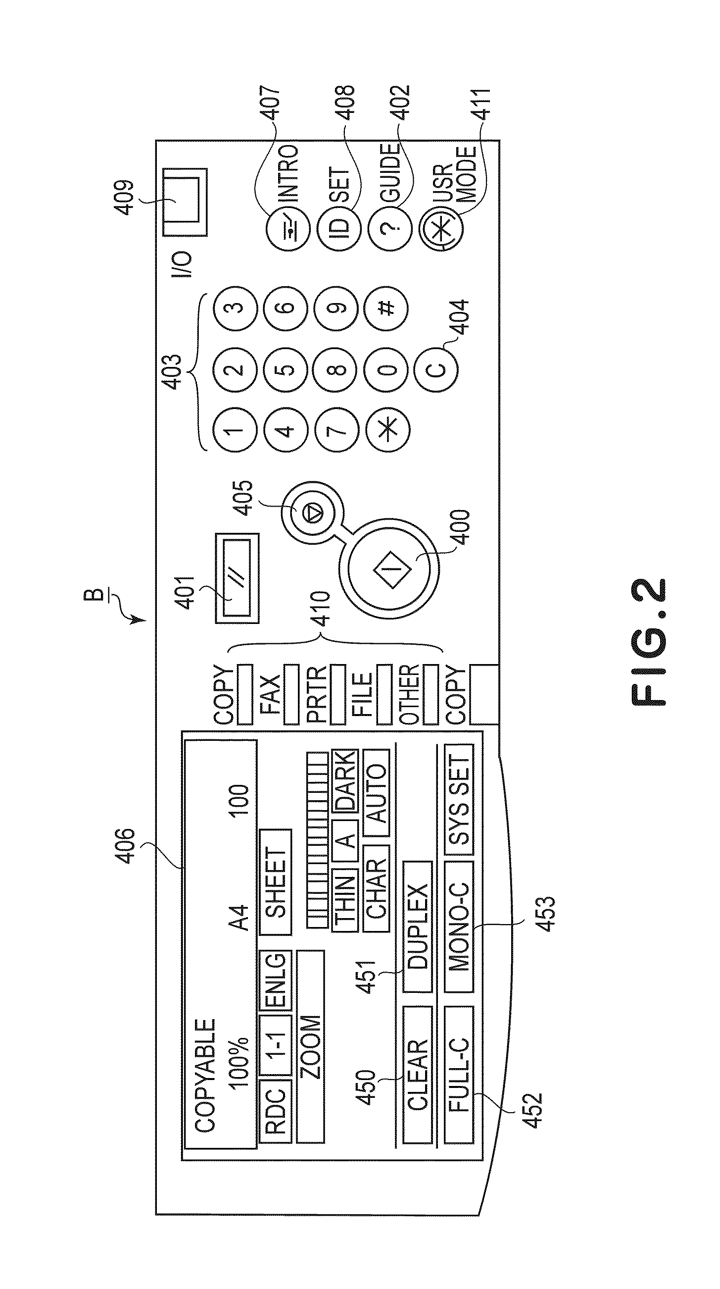
[0033]FIG. 1 shows a schematic sectional view of a general structure of a four-color based full color image forming apparatus, as an embodiment of the image forming apparatus of the present invention, of an electrophotographic type, a tandem type and an intermediary transfer type. This apparatus 100 is a multi-function machine, which functions as a copying machine, a printer and a facsimile machine, capable of forming an image which has been subjected to glossing (gloss processing) with clear toner (transparent toner). FIG. 2 is a plan view of an operation display portion B. Part (a) of FIG. 3 is a schematic block diagram of a control system.

[0034]A reference symbol K represents a controller (controlling means) which effects centralized control of the apparatus 100. The controller K includes a CPU (computing portion) and a storing portion (ROM, RAM). The reference numeral 1000 represents an external input device (external host device), such as a personal com...

verification experiment 1

(8) Verification Experiment 1

[0105]A verification experiment on the change in gloss by a difference of the order of formation (provision) of the clear toner was conducted. The verification was made with respect to two types of the recording material S including plain paper (paper gloss of about 6%) having basis weight of 80 g / m2 and gloss coated paper (paper gloss of 30%) having basis weight of 128 g / m2. With respect to the plain paper used for the verification, the process speed was 200 mm / sec and the control temperature (fixing temperature) of the fixing device 19 was 180° C. Further, with respect to the coated paper, the process speed was 100 mm / sec and the control temperature of the fixing device 19 was 180° C. As the toners, the color toner and the clear toner which had the melt viscosity characteristic shown in (b) of FIG. 3 were used.

[0106]In the verification in this embodiment, color images of three levels of the color toner amount of 60%, 120% and 180% were used. With respe...

embodiment 2

(1) Mixed Gloss Mode

[0112]In this embodiment, the description will be made with respect to control capable of providing variations in level of an increase in gloss or a decrease in gloss in the case where the mixed gloss correction key ((a) of FIG. 5) described in Embodiment 1 is selected. Incidentally, the image forming apparatus used is similar to that used in Embodiment 1. Further, in the following, as the gloss designation image, the case where it is discriminated and designated as a certain area will be described as an example but a similar operation is performed also in the case where it is discriminated and designated as the character information or the object such as color information as described with reference to (a) to (f) of FIG. 6.

[0113]The image formation of the color toner image and the clear toner image and the fixing step in the case where the mixed gloss correction key is selected will be described below. Incidentally, also in this embodiment, similarly as in Embod...


PUM


Abstract

An image forming apparatus includes a color toner image forming portion for forming a toner image with a color toner on a recording material; a clear toner image forming portion for forming a toner image with a clear toner on the recording material, wherein the clear toner has a melt viscosity, at a fixing temperature, higher than that of the color toner; a fixing device for fixing the toner image formed on the recording material; an obtaining portion for obtaining information on an area in which designated glossiness is partly increased, partly decreased, or partly increased and decreased; and a control device for determining the order of formation of the toner image with the color toner and the toner image with the clear toner on the recording material depending on the information obtained by the obtaining portion.

Description

FIELD OF THE INVENTION AND RELATED ART[0001]The present invention relates to an image forming apparatus, such as a printer or a copying machine, capable of effective image formation by color toner and clear toner (transparent toner).[0002]In recent years, an electrophotographic apparatus using the clear toner has been proposed. Various manners of representation can be realized by using the clear toner, so that added value of an output product is improved. Examples of an image forming method using the clear toner may include a method in which a color toner image and a clear toner image are successively formed on a recording material and then are fixed at one time. Further, as described in Japanese Laid-Open Patent Application (JP-A)2002-318482 and JP-A 2006-251722, a two-time fixing method in which the color toner image is formed and once fixed on the recording material and thereon the clear toner image is formed and then fixed may also be included.[0003]On the other hand, as a using...

Claims


Application Information

Patent Timeline
IPC IPC(8): G03G15/20
CPCG03G2215/0081G03G15/0194G03G15/6585G03G15/01G03G15/16
Inventor TAKEMURA, TAICHI
Owner CANON KK
Why Eureka
Try Eureka