Rechargeable battery

Active Publication Date: 2011-07-28
ROBERT BOSCH GMBH +1
View PDF6 Cites 28 Cited by
  • Summary
  • Abstract
  • Description
  • Claims
  • Application Information

AI Technical Summary

Benefits of technology

[0008]An aspect of the present invention provides a rechargeable battery that prevents or reduces the likelihood of a short circuit du

Problems solved by technology

A short circuit due to condensed water within the case may accelerate degradation of a rechargeable battery, a

Method used


Image

  • Rechargeable battery
  • Rechargeable battery
  • Rechargeable battery

Examples


Embodiment Construction

[0020]Example embodiments will now be described more fully hereinafter with reference to the accompanying drawings; however, they may be embodied in different forms and should not be construed as limited to the embodiments set forth herein.

[0021]Rather, these embodiments are provided so that this disclosure will be thorough and complete, and will fully convey the scope of the invention to those skilled in the art.

[0022]Hereinafter, embodiments will be described in detail with reference to the accompanying drawings.

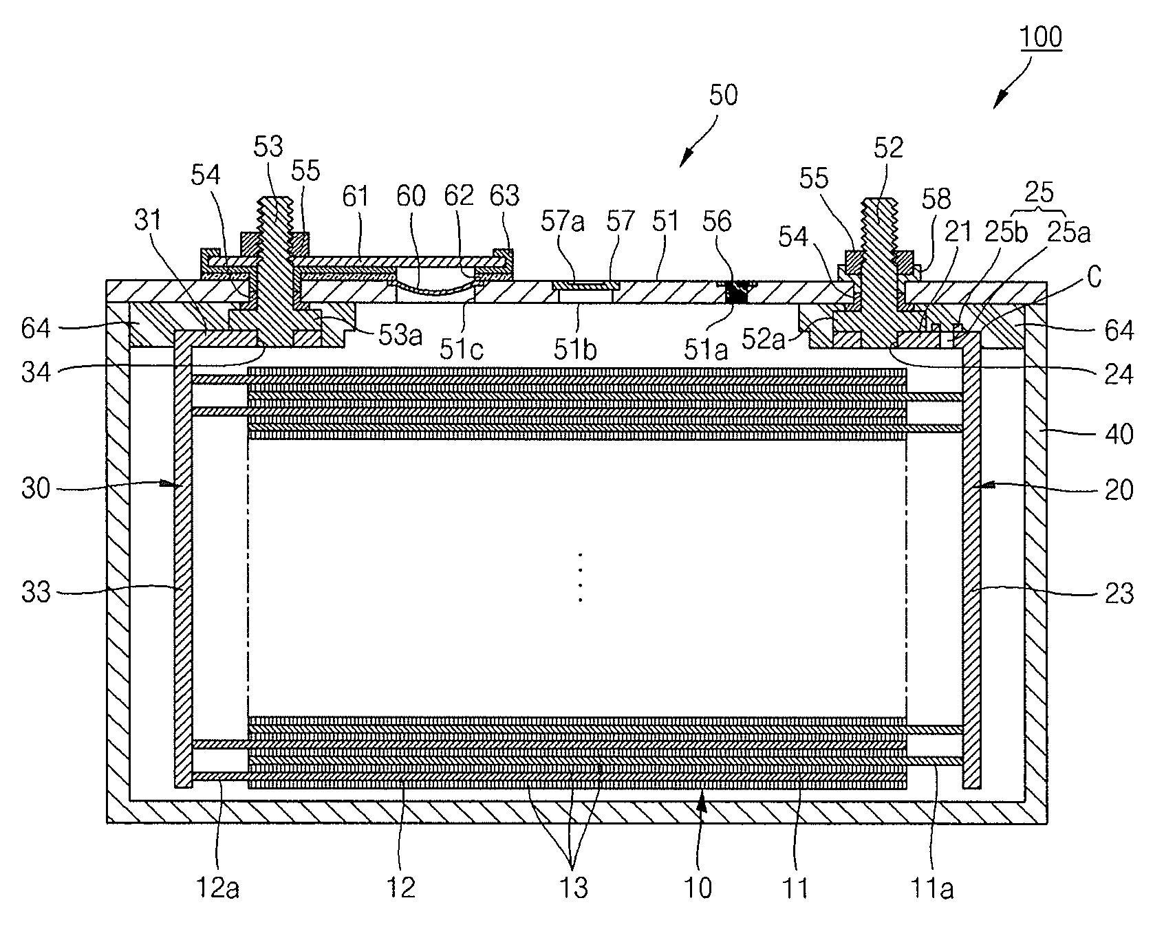
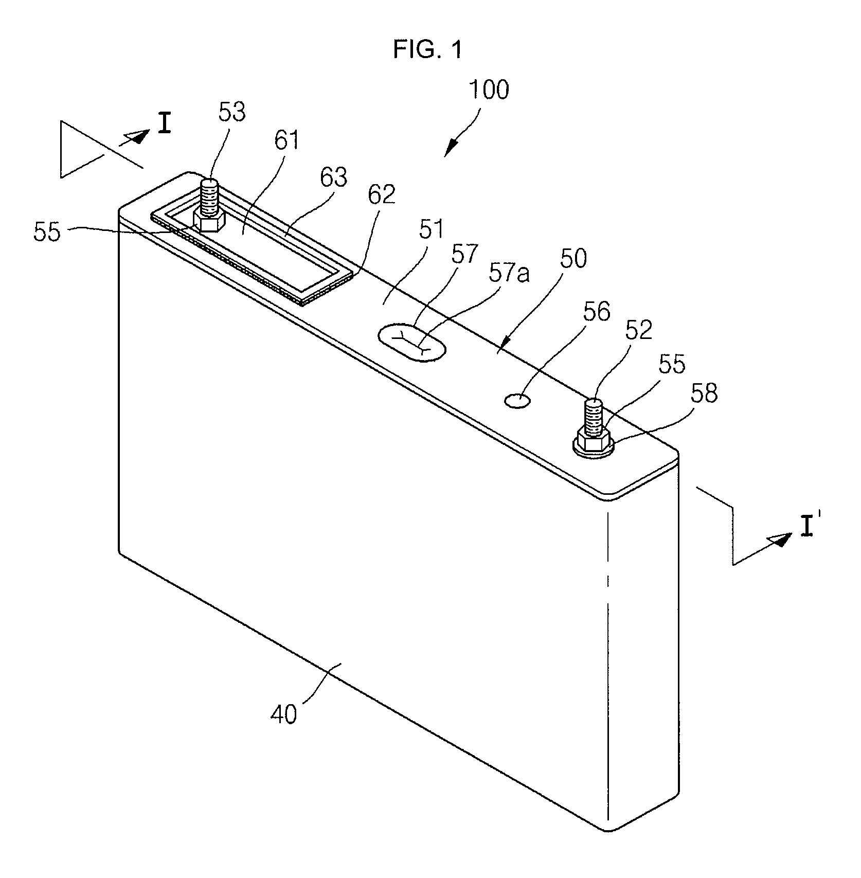
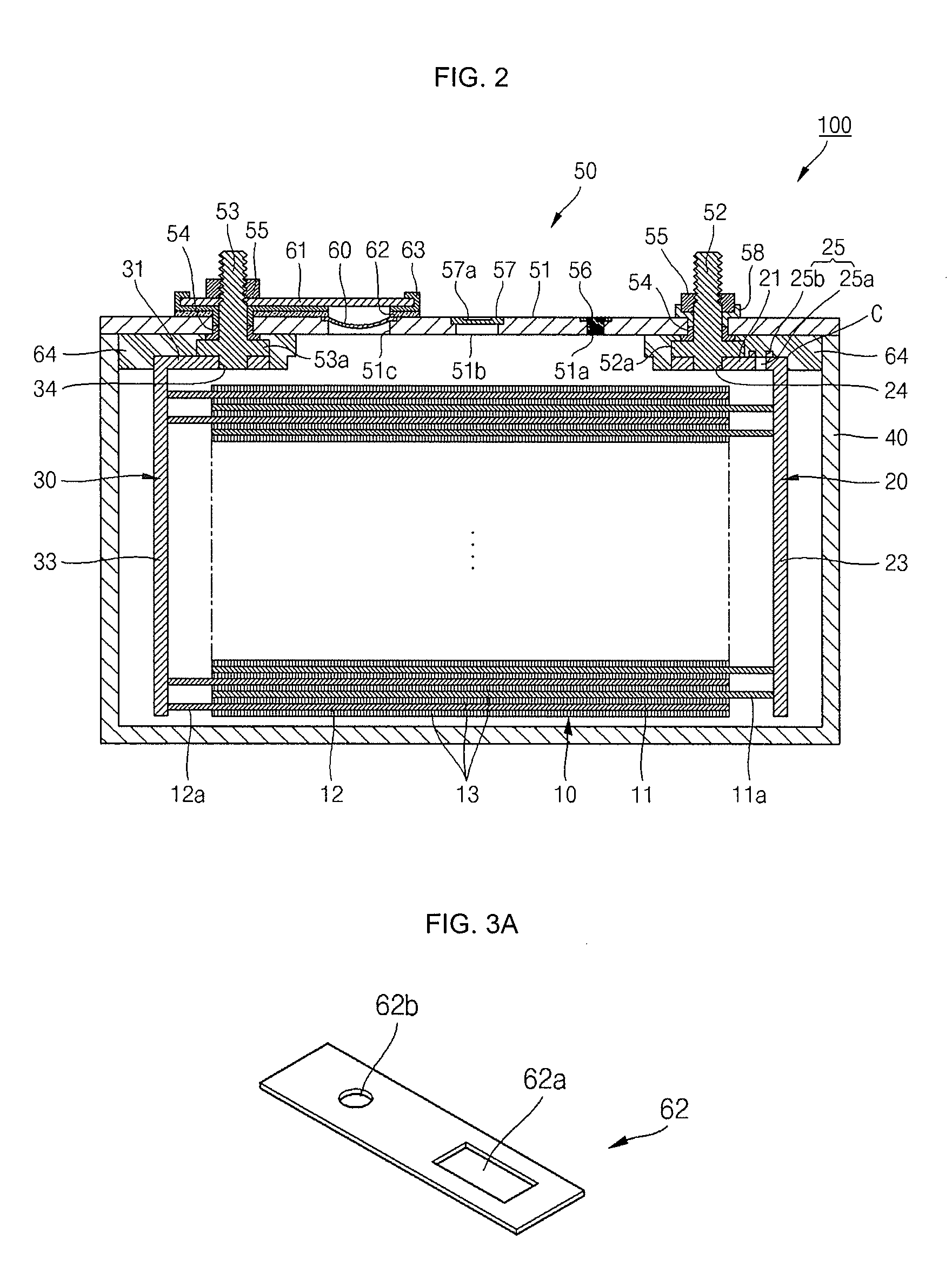
[0023]FIG. 1 is a perspective view illustrating a rechargeable battery according to an embodiment. FIG. 2 is a cross-sectional view taken along line I-I′ of FIG. 1. FIG. 3A is a perspective view illustrating a sealing layer of FIG. 2A. FIG. 3B is a perspective view illustrating another example of the sealing layer of FIG. 3A. FIG. 3C is a perspective view illustrating another example of the sealing layer of FIG. 3A.

[0024]Referring to FIGS. 1 and 2, a rechargeable battery 1...


PUM


Abstract

A rechargeable battery includes an electrode assembly including a first electrode plate, a second electrode plate, and a separator between the first electrode plate and the second electrode plate; a case housing the electrode assembly; and a cap assembly coupled to the case, wherein the cap assembly includes a cap plate sealing the case and having a short circuit opening; a first short circuit plate installed at the short circuit opening of the cap plate; a second short circuit plate on an exterior of the cap plate and spaced from the cap plate to cover the short circuit opening; and a sealing layer between the second short circuit plate and the cap plate.

Description

CROSS-REFERENCE TO RELATED APPLICATION[0001]This application claims priority to and the benefit of Korean Patent Application No. 10-2010-0007046, filed Jan. 26, 2010, in the Korean Intellectual Property Office, the disclosure of which is incorporated by reference herein in its entirety.BACKGROUND[0002]1. Field[0003]Embodiments relate to a rechargeable battery.[0004]2. Description of the Related Art[0005]Unlike a primary battery that is not rechargeable, a rechargeable battery is dischargeable and rechargeable. A low capacity battery having a battery cell packaged in the form of a pack is generally used for a small, portable electronic device such as a mobile phone and a camcorder. A large capacity battery having tens of battery packs interconnected is often used as a power source for driving a motor of a hybrid vehicle and the like.[0006]The rechargeable battery is formed in a variety of shapes such as a prismatic shape, a cylinder shape, and the like. The rechargeable battery typic...

Claims


Application Information

Patent Timeline
IPC IPC(8): H01M2/02H01M50/15H01M50/184H01M50/186H01M50/193
CPCH01M2/0456H01M2/08Y02T10/7011H01M10/052H01M2/345Y02E60/10H01M50/578Y02P70/50H01M50/184H01M50/186H01M50/193H01M50/15H01M2200/00H01M2200/20H01M50/103H01M50/571H01M50/572Y02T10/70
Inventor BYUN, SANGWONCHOI, SOOSEOKKIM, SUNGBAE
Owner ROBERT BOSCH GMBH
Why Eureka
Try Eureka