Plasma cutting machine exhaust apparatus and method

a plasma cutting machine and exhaust system technology, applied in ventilation systems, heating types, stoves or ranges, etc., can solve problems such as energy waste, achieve the effects of reducing energy consumption, facilitating rapid air movement, and reducing energy loss during the cutting process

Inactive Publication Date: 2011-07-28
J WALTER THOMPSON
View PDF13 Cites 3 Cited by
  • Summary
  • Abstract
  • Description
  • Claims
  • Application Information

AI Technical Summary

Benefits of technology

[0005]A primary object of the present invention is to provide exhaust systems for plasma cutting machines which use an outside air supply instead of heated or air conditioned room air to save on energy costs.
[0007]The exhaust system for plasma cutting machines of the present invention includes a cutting table having integral intake and exhaust air ducts along the bottom of the cutting table. These ducts of the cutting table connect to intake and exhaust air ducts of the exhaust system. The other end of the intake and exhaust air ducts connect to openings in the exterior walls or roof of the building. The invention uses an outside air intake supply for the exhaust system of the cutting tables. Fan pressure is introduced into the duct system to facilitate rapid air movement and exhaust airflow through the table.
[0008]Accordingly, the exhaust system of the present invention uses an outside air supply for the table exhaust system. By using an outside air supply for the exhaust system, heated or cooled shop air is not drawn into the table and removed from the building by the table exhaust. As such, energy loss during the cutting process is virtually eliminated.
[0009]Additionally, the exhaust system of the present invention may control the airflow to select zones of the cutting table. This may increase the energy savings, efficiency and performance of the plasma cutting machine.

Problems solved by technology

When this heated or cooled air is removed from inside of the building, energy is wasted.

Method used


Image

  • Plasma cutting machine exhaust apparatus and method
  • Plasma cutting machine exhaust apparatus and method
  • Plasma cutting machine exhaust apparatus and method

Examples


Embodiment Construction

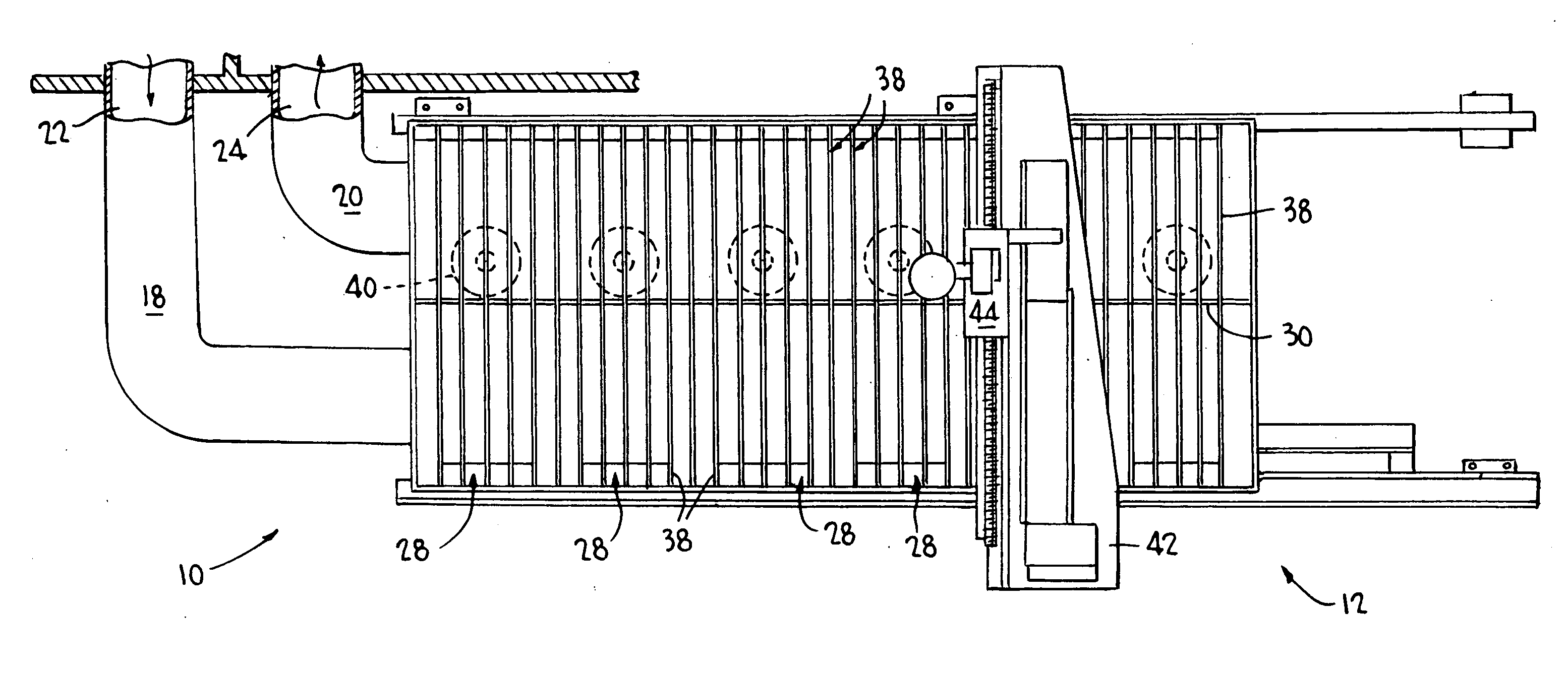
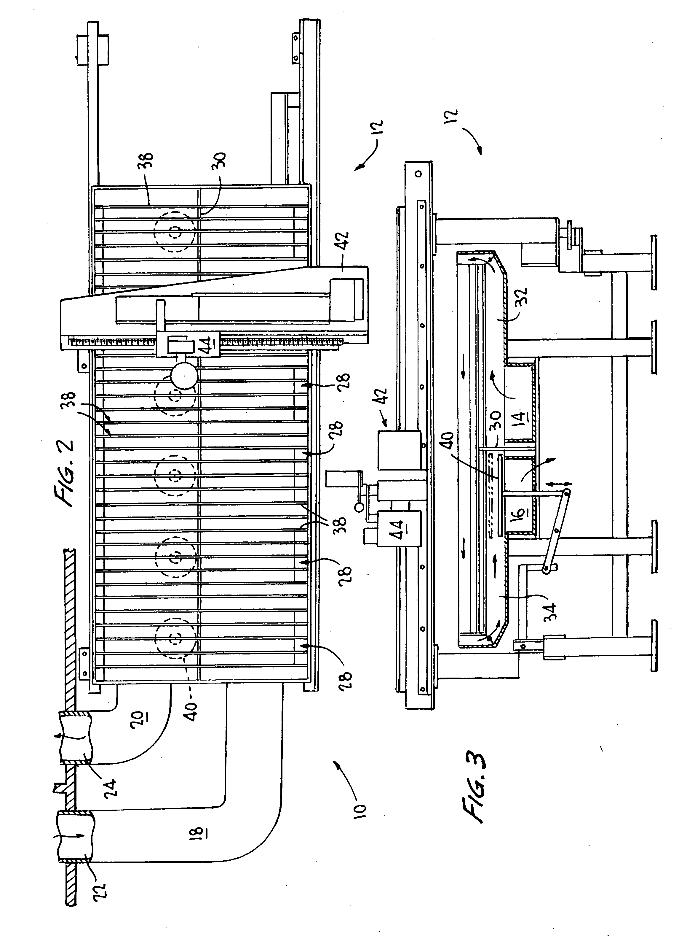
[0018]Referring to FIGS. 2-6, the present invention relates to an exhaust system 10 for a plasma cutting machine and its method of use. The exhaust system 10 for plasma cutting machines includes a cutting table 12 which includes an integral intake duct 14 and exhaust duct 16 along a bottom of the cutting table 12. This design uses an outside air intake to supply the cutting table 12 and exhaust system 10 thereof with air. The terms “outside air intake” or “external source of air” or variations thereof as used herein mean an intake of air from a source outside of a closed area having the plasma cutting machine, e.g., air from outside of a building housing the plasma cutting machine. This design also exhausts air from the cutting table 12 through the exhaust system 10 to an outside air exhaust opening, e.g., outside of a building housing the plasma cutting machine, as disclosed hereafter.

[0019]More specifically, the exhaust system 10 has an intake air duct 18 and an exhaust air duct 2...


PUM

PropertyMeasurementUnit
perimeteraaaaaaaaaa
energyaaaaaaaaaa
energy efficientaaaaaaaaaa

Abstract

An exhaust system for a plasma cutting machine which uses an outside air supply to provide needed airflow to a cutting table thereof is disclosed. Airflow into the cutting table may be controlled and directed to select zones of the cutting table.

Description

RELATED APPLICATION[0001]The application hereby claims the benefit under 35 U.S.C. §119(e) of U.S. Provisional Application Ser. No. 61 / 282,325, filed Jan. 22, 2010, entitled PLASMA CUTTING MACHINE EXHAUST APPARATUS AND METHOD, which application is incorporated herein by reference in its entirety.FIELD OF INVENTION[0002]The present invention relates to exhaust systems for plasma cutting machines and methods of using the same.BACKGROUND OF INVENTION[0003]Typical plasma cutting machines have a cutting table with one or more exhaust holes in a bottom or a side of the cutting table. FIG. 1 illustrates a typical prior art plasma cutting machine 100. Exhaust holes (not shown) in the plasma cutting table 102 exit at exhaust duct 104 to an opening 106 in a building wall or roof to remove smoke which is generated during the cutting of a sheet of metal 108 by the plasma cutting torch 110. A fan (not shown) is placed in the duct to draw exhaust air from the cutting table to the outside of the b...

Claims


Application Information

Patent Timeline
Patent Type & Authority Applications(United States)
IPC IPC(8): F24F7/04B23K10/00
CPCB23K10/00B23K37/0235B23K2201/18B23K37/0461B23K37/0408B23K2101/18
Inventor TOBEN, JOHN J.LAVENZ, GERALD J.DICKINSON, GARY L.
Owner J WALTER THOMPSON
Why Eureka
Try Eureka