
Vascular remodeling device

a technology of vascular remodeling and vascular valves, applied in the field of vascular remodeling devices, can solve the problems of occlusion of arterial vessels, stroke, and/or death, and achieve the effect of inhibiting the herniation of embolic materials

Active Publication Date: 2011-07-28
TYCO HEALTHCARE GRP LP
View PDF110 Cites 61 Cited by
  • Summary
  • Abstract
  • Description
  • Claims
  • Application Information

AI Technical Summary

Benefits of technology

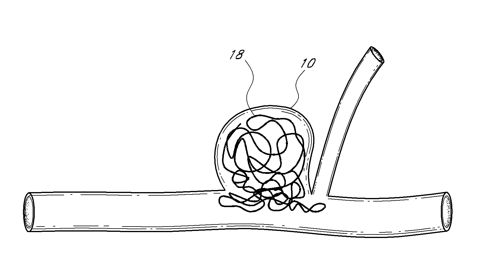
[0009]In some embodiments, a method of treating an aneurysm is provided. The aneurysm is at a junction of a bifurcation having an afferent vessel and efferent vessels. The aneurysm has a neck and a fundus. The method comprises advancing a catheter proximate to the junction of the bifurcation. The catheter at least partially contains a device in a compressed state. The device comprises a plurality of filaments extending between the proximal end and the distal end and coupled at the proximal end and at the distal end. The method further comprises deploying the device from at least partially inside the catheter to outside the catheter at the junction of the bifurcation. During deployment, the device self-expands to conform in an expanded state to the junction of the bifurcation. After deployment, and while the proximal end of the device is connected to the catheter, the device acts as a scaffolding to inhibit herniation of objects out of the neck of the aneurysm and permits perfusion of fluid to the efferent vessels. The method further comprises retracting the device at least partially back inside the catheter and withdrawing the catheter and the device.
[0010]In some embodiments, an intraluminal apparatus is provided. The intraluminal apparatus comprises a catheter and a device. The device has a distal end and a proximal end and comprises a plurality of filaments extending between the proximal end and the distal end and coupled at the proximal end and at the distal end. The device is configured to self-expand from a compressed state upon deployment from at least partially inside the catheter to outside the catheter to conform in an expanded state to a junction of a bifurcation. The bifurcation has an afferent vessel, efferent vessels, and an aneurysm having a neck and a fundus. The device is configured to act as a scaffolding to inhibit herniation of objects out of the neck of the aneurysm and to permit perfusion of fluid to the efferent vessels while the proximal end of the device is connected to the catheter. The device is retractable from the expanded state at least partially back inside the catheter.
[0011]In some embodiments, an intraluminal apparatus is provided. The intraluminal apparatus comprises a catheter and a device having a distal end and a proximal end. The device is configured to self-expand upon deployment from at least partially inside the catheter to outside the catheter. The device is configured to conform in an expanded state to a junction of a bifurcation having an afferent vessel, efferent vessels, and an aneurysm having a neck and a fundus. The distal end of the device comprises a covering configured to act as a scaffolding to inhibit herniation of embolic material out of the neck of the aneurysm. The device is configured to permit perfusion of fluid to the efferent vessels.
[0012]In some embodiments, a method of treating an aneurysm at a junction of a bifurcation is provided. The bifurcation has an afferent vessel, efferent vessels, and an aneurysm having a neck and a fundus. The method comprises advancing a catheter proximate to the junction of the bifurcation. The catheter at least partially contains a device in a compressed state. The device comprises a plurality of filaments and a central filament. The method further comprises deploying the device from at least partially inside the catheter to outside the catheter at the junction of the bifurcation. During deployment, the device self-expands to conform to the junction of the bifurcation. The method further comprises reshaping the deployed device by using the central filament to adjust a distance between a proximal end of the device and a distal end of the device. After deployment, the device acts as a scaffolding to inhibit herniation of objects out of the neck of the aneurysm and permits perfusion of fluid to the efferent vessels. The method further comprises retracting the device at least partially back inside the catheter and withdrawing the catheter and the device.

Problems solved by technology

Herniation of coils may cause arterial occlusion, stroke, and / or death.

Method used


Image

  • Vascular remodeling device
  • Vascular remodeling device
  • Vascular remodeling device

Examples


Embodiment Construction

[0045]Although certain embodiments and examples are described below, those of skill in the art will appreciate that the invention extends beyond the specifically disclosed embodiments and / or uses and obvious modifications and equivalents thereof. Thus, it is intended that the scope of the invention herein disclosed should not be limited by any particular embodiments described below.

[0046]FIG. 5 illustrates an example embodiment of a generally spherical vascular remodeling device 80. It will be appreciated that the device 80 may be more compliant than the vasculature in which it is deployed such that it may be somewhat misshapen (e.g., non-spherical, for example as illustrated in FIG. 9B) after being deployed, and that the phrase “generally spherical” describes the shape of the device 80 when in an expanded (e.g., fully expanded) state outside of vasculature. Additionally, the phrase “generally spherical” distinguishes the device 80, which is generally uniform in each dimension in an...


PUM


Abstract

An intraluminal apparatus including a catheter and device is positionable at a junction of afferent and efferent vessels of a bifurcation having an aneurysm. After positioning the device to substantially conform the device to the shape of the junction, the device acts as a scaffolding to inhibit herniation of objects out of the aneurysm and the device permits perfusion to the efferent vessels. Positioning the device may include deployment and optional release from a catheter. Embolic material may be inserted in the aneurysm before or after positioning the device. The device may have a proximal end, a distal end, and a plurality of filaments extending between and coupled at the proximal end and the distal end. The device may include a central filament configured to reshape the device. The distal end of the device may include a covering. The device may be football shaped, pumpkin shaped, or acorn shaped.

Description

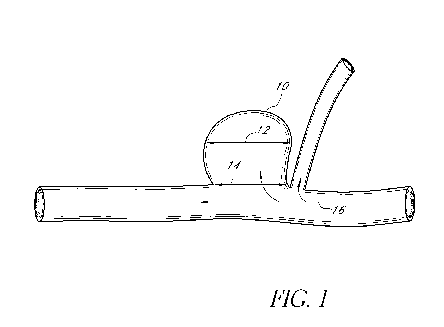
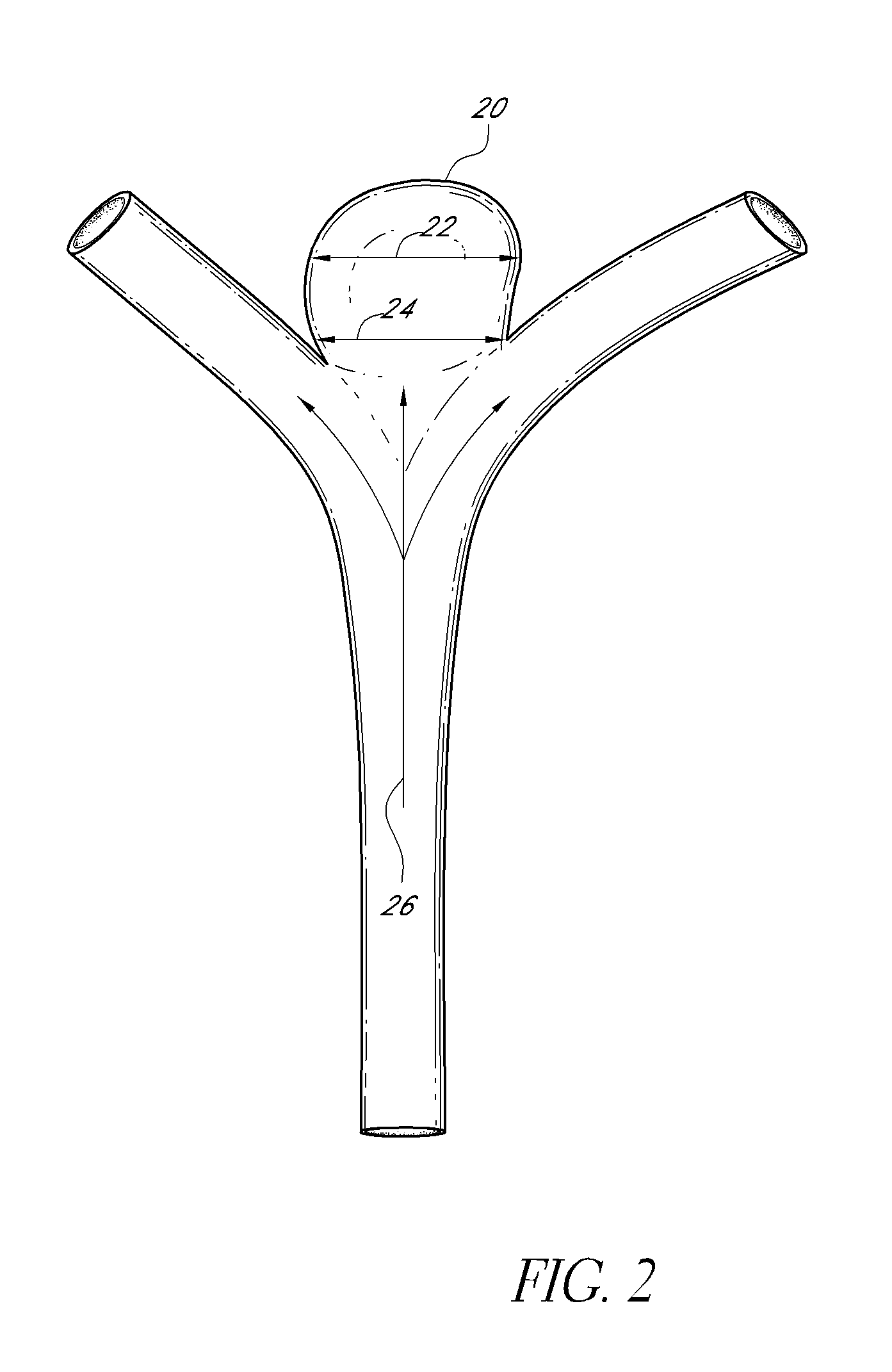
[0001]This application claims priority benefit of U.S. Provisional Patent Application No. 61 / 299,254, filed Jan. 28, 2010, which is incorporated herein by reference in its entirety.BACKGROUND[0002]1. Field[0003]The present application generally relates to vascular remodeling devices and to the manner of their positioning in vessels, and, more particularly, to the matter of their positioning at the junction of neurovascular bifurcations having an aneurysm.[0004]2. Description of Related Art[0005]Neurovascular or cerebral aneurysms affect about 5% of the population. Aneurysms may be located, for example, along arterial side walls (e.g., the aneurysm 10 illustrated in FIG. 1) and at arterial bifurcations (e.g., the aneurysm 20 illustrated in FIG. 2). The direction of fluid flow is generally indicated by the arrows 16, 26. The aneurysms 10, 20 each have a fundus 12, 22, a neck 14, 24, and a fundus-to-neck ratio or “neck ratio.” If the neck ratio is greater than 2 to 1 or if the neck 14,...

Claims


Application Information

Patent Timeline
Patent Type & Authority Applications(United States)
IPC IPC(8): A61M29/00A61F2/82A61F2/86
CPCA61B17/12118A61B17/1214A61B17/12172A61F2/856A61F2230/0071A61F2002/823A61F2002/9528A61F2002/9534A61F2230/0063A61F2/86
Inventor HUYNH, ANDYMOLAEI, MASOUDSCHUMAN, VICTORIASHRIVASTAVA, SANJAYSLEE, EARLTRAN, QUANG
Owner TYCO HEALTHCARE GRP LP
Learn More