Self locking adjustable blade guide for band saw

Active Publication Date: 2011-08-04
NORWOOD IND
View PDF29 Cites 6 Cited by
  • Summary
  • Abstract
  • Description
  • Claims
  • Application Information

AI Technical Summary

Benefits of technology

[0011]The present invention provides a saw head for a sawmill, said saw head comprising: a frame, a drive driving a saw blade, and a blade guide contacting said saw blade and capable of decreasing transverse and/or vertical movement of the band saw blade when said blade is in motion. The blade guide is affixed to a guide support which is slidably engaged to the frame. The guide support has a guide support adjuster pivotally connected the

Problems solved by technology

One problem faced with band saws having large band saw blades is the tensioning of said blade.
The portion of the saw blade between the two band wheels is often exposed and largely unrestrained; complex forces on the blade as it passes through the log result in substantial and undesired transverse motion of the blade,

Method used


Image

  • Self locking adjustable blade guide for band saw
  • Self locking adjustable blade guide for band saw
  • Self locking adjustable blade guide for band saw

Examples


Embodiment Construction

[0026]The present invention provides a simple and effective, adjustable blade guide mechanism for a band saw. The adjustable blade guide is self locking in that it can be adjusted to a desired position without the need for screwing or unscrewing restraining bolts. The blade guide's design enables it to be quickly adjusted with one hand by an operator. The self locking feature reduces the number of steps required by the operator in adjusting the blade guide, thus increasing efficiency and safety of operation.

[0027]An embodiment of the present invention will now be described as shown in FIGS. 1-5 and 9.

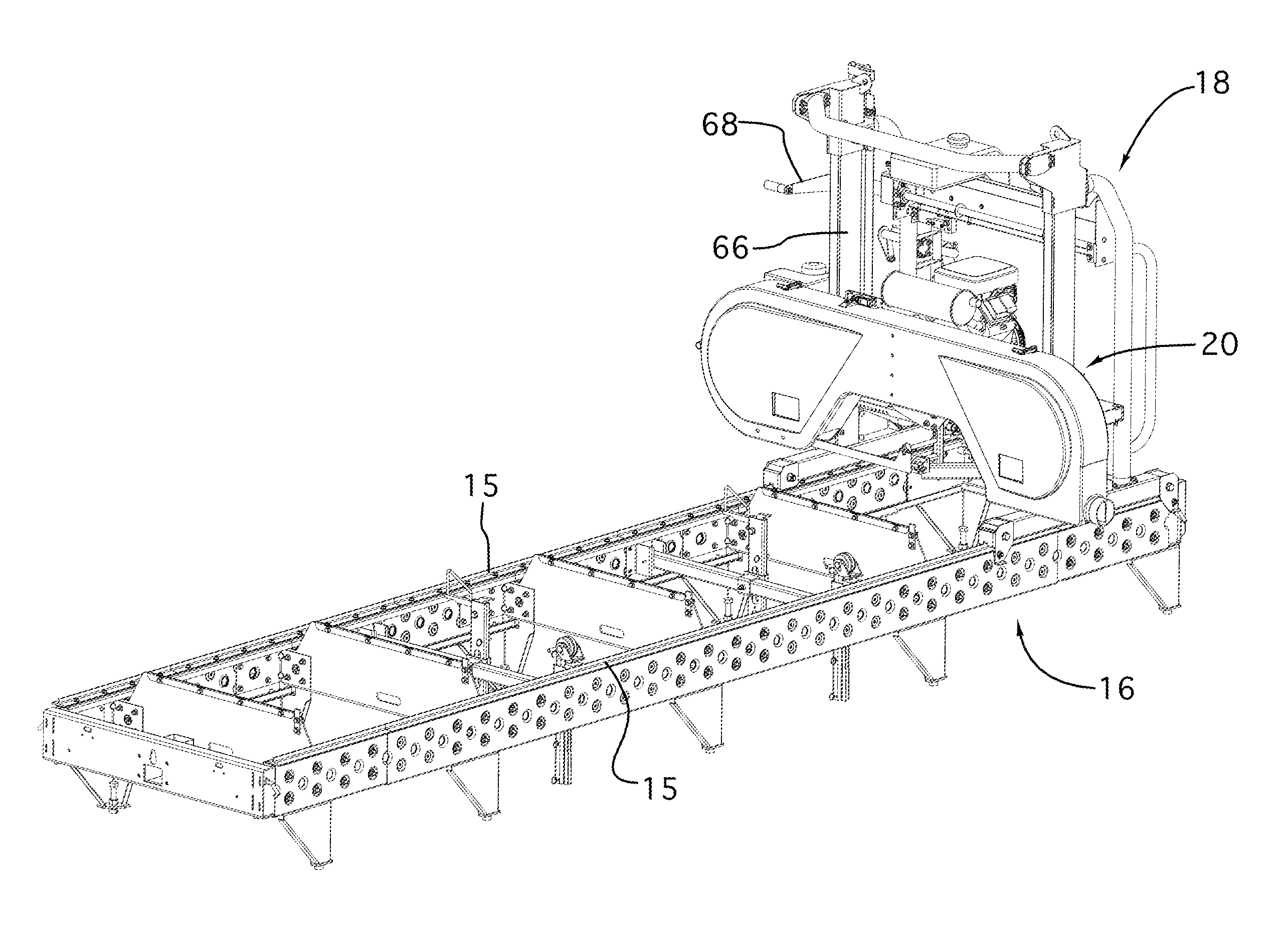
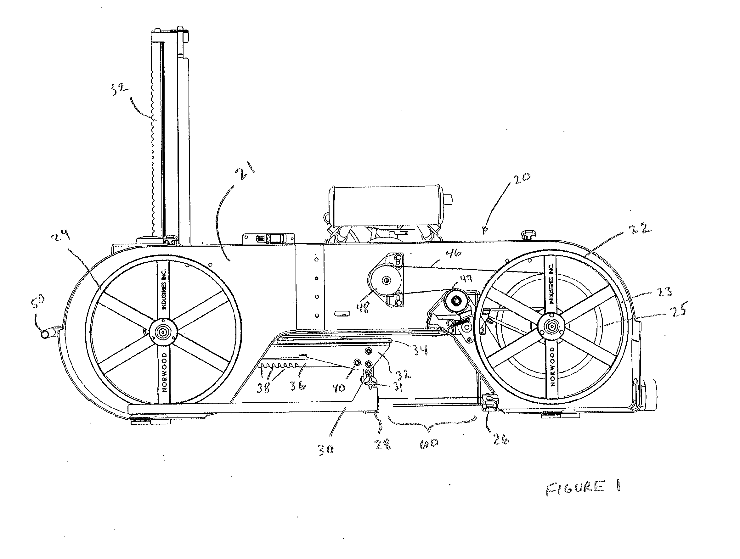
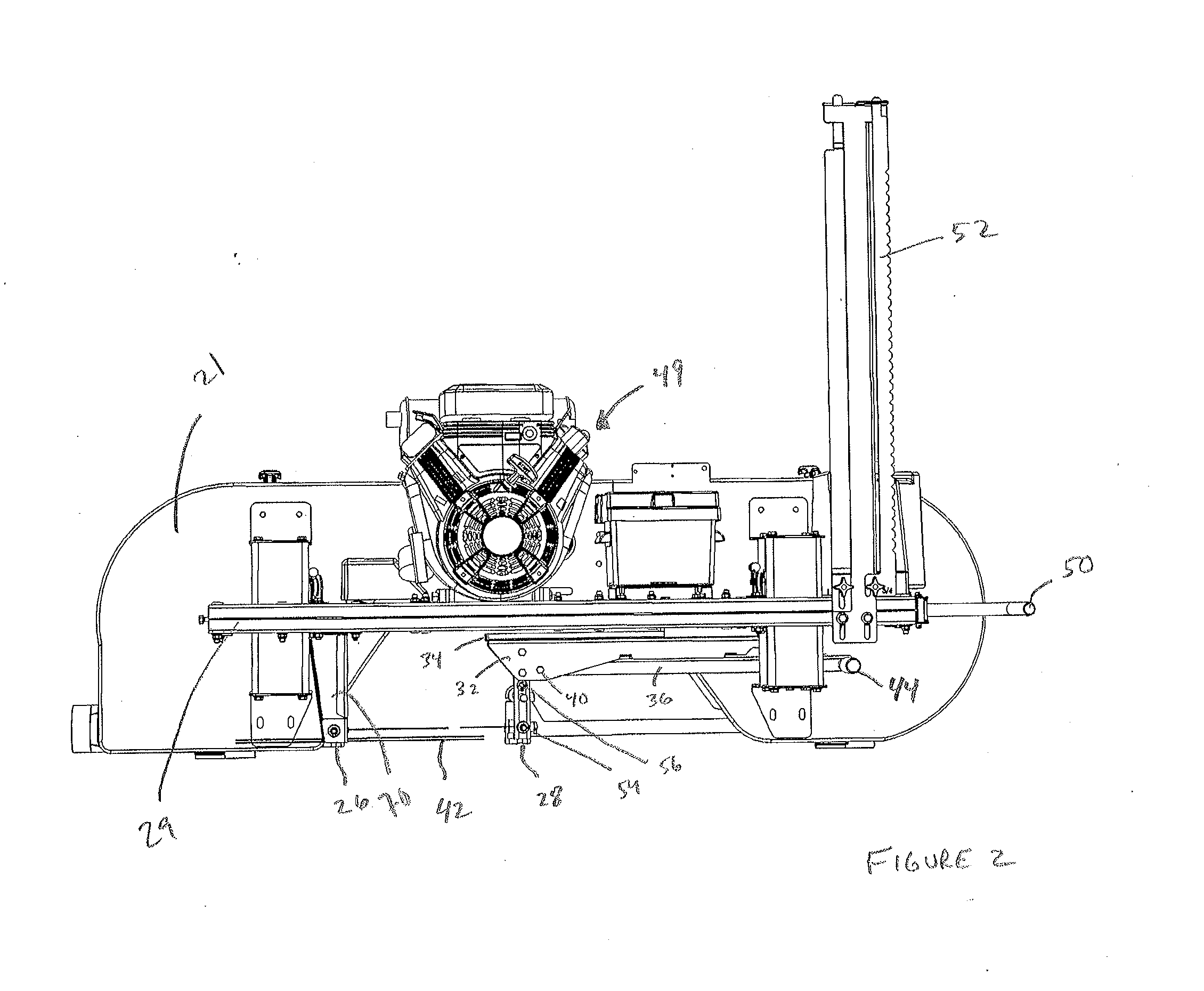
[0028]Band saw head 20 is designed to be used as part of a sawmill (as shown in FIG. 9 only). Briefly, band saw head 20 is fitted to carriage 18 which is capable of longitudinal displacement on rails 15 of sawmill base 16. Band saw head 20 is capable of vertical displacement in relation to sawmill base 16 through displacement along depth of cut ruler 52. Tension on the blade is controll...


PUM

PropertyMeasurementUnit
Displacementaaaaaaaaaa

Abstract

An adjustable blade guide for a band saw such as a band saw on a sawmill utilized for sawing lumber. The blade guide is easily adjusted to account for variations in the diameter of the lumber to be cut, and is self locking.

Description

FIELD OF THE INVENTION[0001]The present invention relates to an adjustable blade guide for a band saw such as a band saw on a sawmill utilized for sawing lumber. The blade guide is easily adjusted to account for variations in the diameter of the lumber to be cut, and is self locking.BACKGROUND OF THE INVENTION[0002]A conventional band saw is often used in sawmills. Such a band saw typically has a relatively large, circular, band saw blade, mounted along the path of travel of a log placed on a suitable moving bed with a drive mechanism for advancing the log against the blade. Alternatively, the log remains stationary and the band saw is mounted on a carriage which is capable of transverse displacement along the log.[0003]One problem faced with band saws having large band saw blades is the tensioning of said blade. The blade moves in a generally circular path, typically around two band wheels, one of which is powered by a motor, either via direct drive or a belt drive. The portion of ...

Claims


Application Information

Patent Timeline
IPC IPC(8): B27B15/04B27B13/10B27B3/10
CPCB23D51/025B23D55/082Y10T83/696Y10T83/7264Y10T83/8878Y10T83/95
Inventor DALE, PETER
Owner NORWOOD IND
Why Eureka
Try Eureka