
Filter apparatus and method of monitoring filter apparatus

a filter apparatus and filter technology, applied in auxillary pretreatment, instruments, separation processes, etc., can solve the problems of filter loss or head loss, filter may lose some capacity or efficiency in filtering air flow, and filter may lose some capacity or efficiency

Inactive Publication Date: 2011-08-04
FREEN PAUL
View PDF52 Cites 310 Cited by
  • Summary
  • Abstract
  • Description
  • Claims
  • Application Information

AI Technical Summary

Benefits of technology

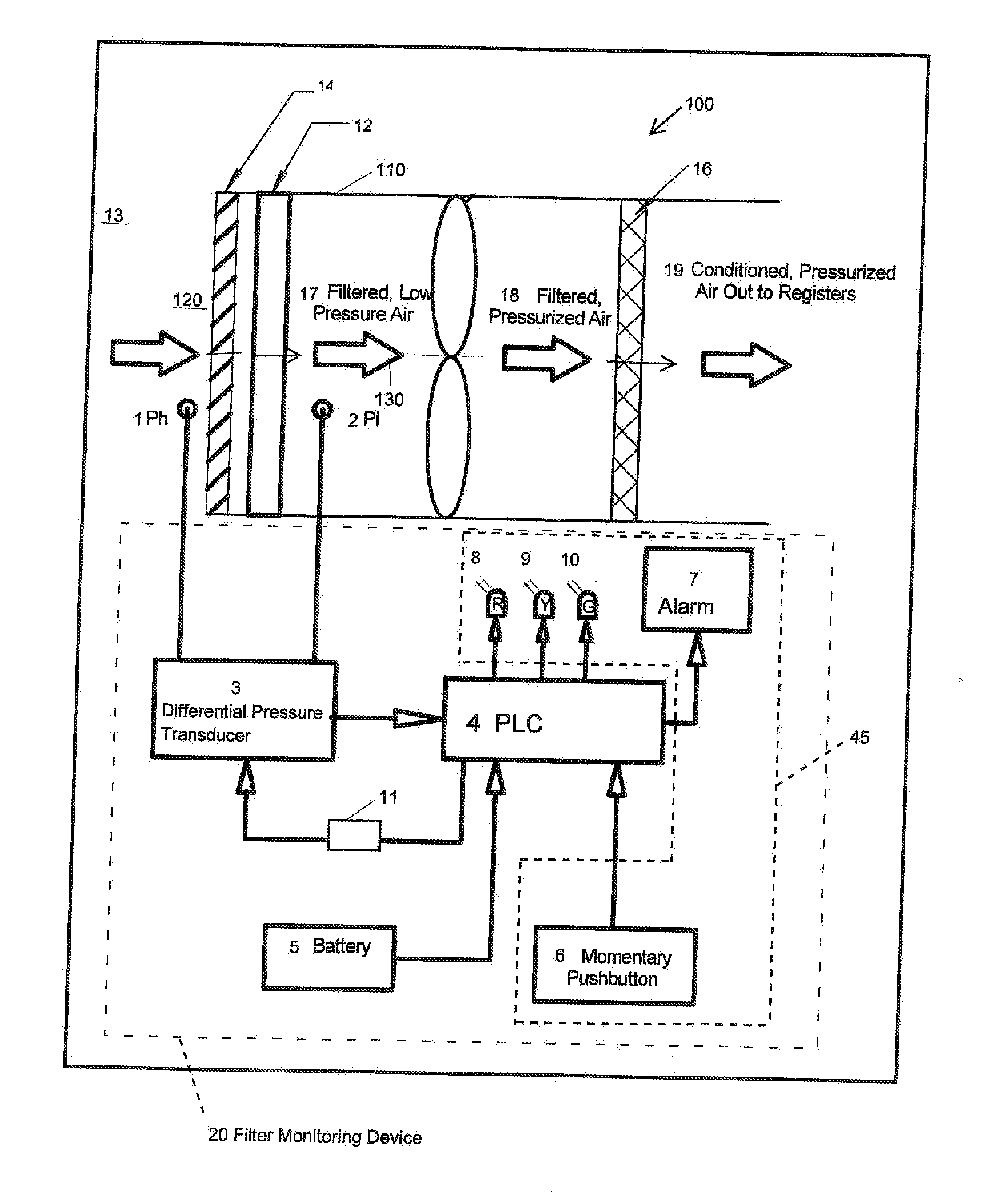
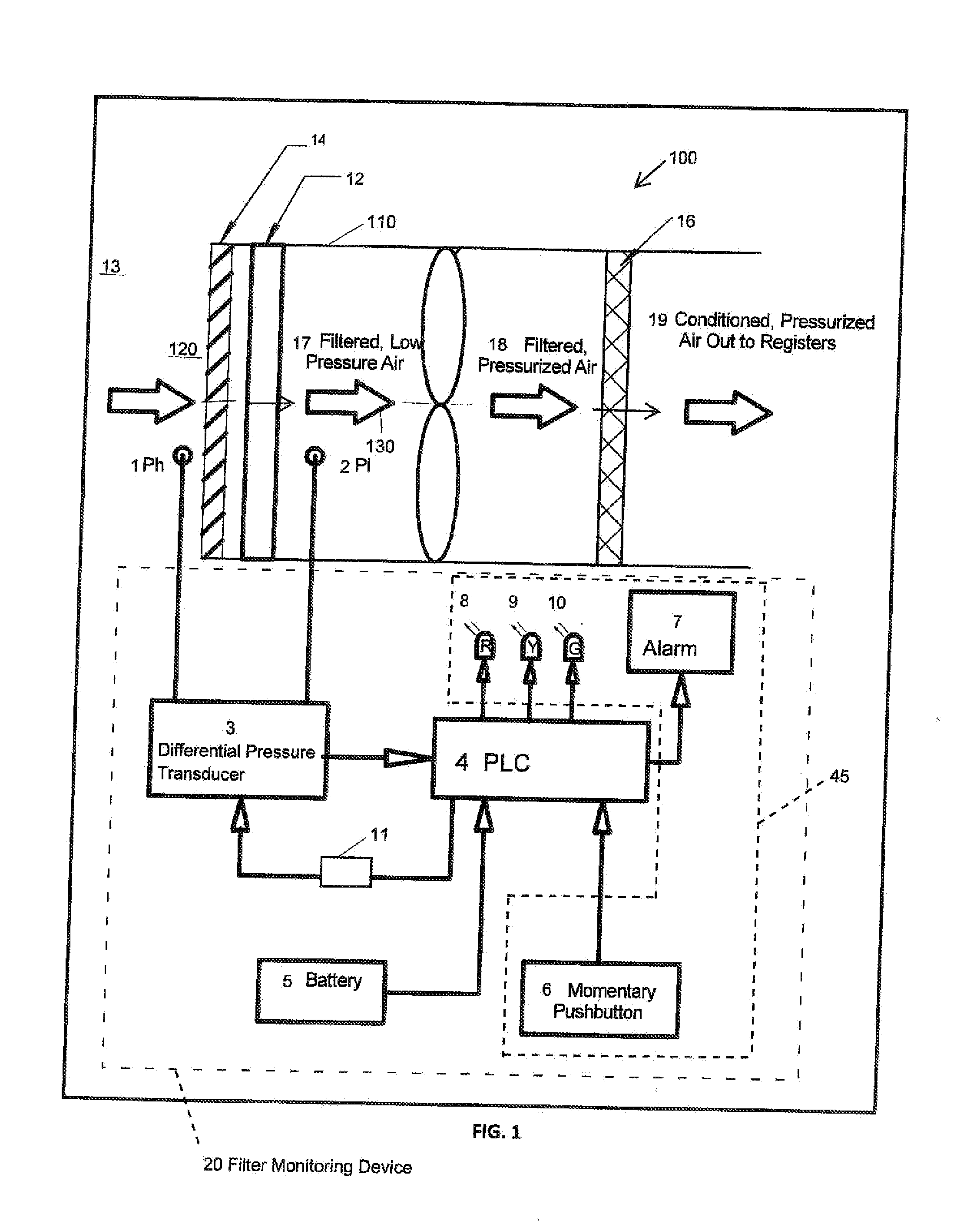
[0008]Embodiments of the invention include methods of monitoring an air filter with a battery-powered filter monitor, where the system filters intake air flowing from an upstream to a downstream side of the filter. Methods may include determining with the filter monitor a first pressure differential between a first air pressure upstream of the filter and a second air pressure downstream of the filter; setting a baseline value at the first pressure differential; allowing extended operation of the filter monitor in a sleep state; intermittently waking the filter monitor, and returning the filter

Problems solved by technology

The filter media of even a new or clean air filter presents some resistance to the air flow, which translates to a pressure loss or head loss (i.e., the pressure differential across the filter) of a magnitude dependent, among other things, on the flow restriction and the velocity of the air flow.
As the porous filter media accumulates impurities, however the filter media further restricts air flow and the pressure loss across the filter increases.
Among other things, the filter may lose some capacity or efficiency in filtering the air flow.
The excess pressure loss may also represent significant energy loss in the HVAC system and result in a higher burden on system equipment.
Such methods of “monitoring” become ineffective, however, if the user (maintenance personnel, homeowner, etc.) fails to periodically and diligently monitor HVAC performance or simply fail to recognize that a filter condition warrants cleaning or replacement.
Many of these prior art devices have, however, proven cumbersome or difficult to use and often are rendered useless without initiative from the user.
Other devices may be effective in specific filtering applications, but may be too expensive for broader applications.

Method used


Image

  • Filter apparatus and method of monitoring filter apparatus
  • Filter apparatus and method of monitoring filter apparatus
  • Filter apparatus and method of monitoring filter apparatus

Examples


Embodiment Construction

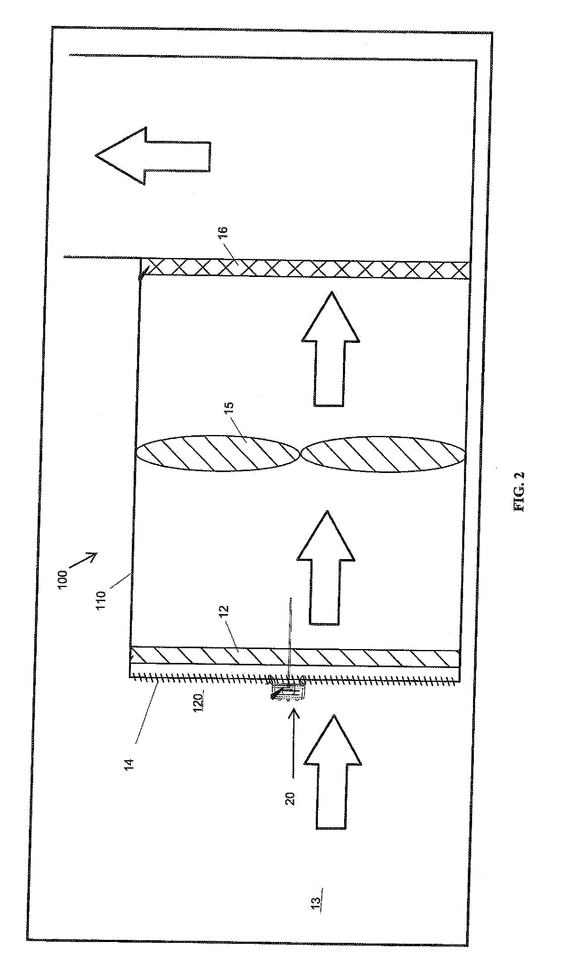
[0024]The principles of the invention are explained by describing in detail, specific and exemplary embodiments of devices, products, and methods for monitoring an HVAC air filter. Those skilled in the art will understand, however, that the invention may be embodied as many other devices, products, and methods. For example, various aspects of the methods and devices may be applied to other filter media and the maintenance of such other filter media. The scope of the invention is not intended to be limited by the details of exemplary embodiments described herein. The scope of the invention should be determined through study of the appended claims.

[0025]Embodiments of the disclosure include a device or apparatus for monitoring an operating condition of an HVAC filter and being responsive to the presence or arrival of a target filter condition. The condition of the HVAC filter is directly correlated to its efficiency in filtering air flowing through the HVAC system and the efficiency o...


PUM

PropertyMeasurementUnit
Pressureaaaaaaaaaa
Threshold limitaaaaaaaaaa

Abstract

Methods, systems, and products for monitoring an air filter. Methods involve determining a difference between a baseline pressure differential and a current pressure differential, the differential pressure between pressure at an upstream side of the filter and pressure at a downstream side of the filter. The baseline pressure differential may be set automatically or by a user. Reaching or exceeding a predetermined threshold triggers an indication of a clogged condition. The method also includes monitoring the air filter condition intermittently. The filter monitor may operate for extended periods in a sleep state and intermittently power up to a wake state to measure the current pressure differential and compare the current pressure differential with a baseline pressure differential.

Description

[0001]The present application claims the benefit of, and priority to, the filing date of U.S. Provisional Application Ser. No. 61 / 337,388, filed on Feb. 3, 2010 (pending). The disclosure is hereby incorporated by reference for all purposes and made a part of the present disclosure.BACKGROUND[0002]The present invention relates to systems, methods, and apparatus for monitoring filter media, particularly an air filter.[0003]Air filters may be employed in a variety of internal flow systems to remove undesireable substances and matter from the flow stream. The present invention is particularly suited for use with air filters employed in heating, ventilating, and air conditioning (‘HVAC’) systems. The air filter is placed in the flow stream generated by the HVAC system, typically near the inlet of the HVAC system. With the air flow directed through the filter media, the filter removes dust, debris, and other impurities from the flow stream (and from the space being serviced (“conditioned ...

Claims


Application Information

Patent Timeline
IPC IPC(8): B01D46/42G01N15/08
CPCG01N15/08B01D46/42B01D46/0086B01D46/446F02M35/09B01D46/444B01D2279/60
Inventor FREEN, PAUL
Owner FREEN PAUL
Learn More