Power transfer device and method

a power transfer device and power supply technology, applied in the direction of electrical apparatus construction details, transportation and packaging, inductance, etc., can solve the problems of adversely affecting all other instruments using the same power supply, and achieve the effect of reducing or minimizing interference signals within the communication bandwidth

Active Publication Date: 2011-08-04
CONVENIENTPOWER HK
View PDF29 Cites 76 Cited by
  • Summary
  • Abstract
  • Description
  • Claims
  • Application Information

AI Technical Summary

Benefits of technology

[0007]The present invention provides, in a first aspect, a power transfer device for charging a wireless communication device having a communication bandwidth, the pow...

Problems solved by technology

The harmonics generated by the constant-switching power converter cause “conducted” electromagnetic interference (EMI) beca...

Method used


Image

  • Power transfer device and method
  • Power transfer device and method
  • Power transfer device and method

Examples


Embodiment Construction

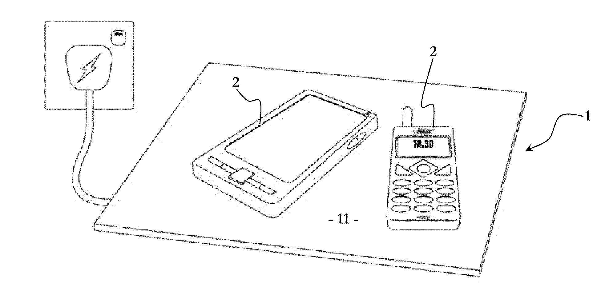
[0037]Referring to the figures, there is provided a power transfer device 1 for charging a wireless communication device 2 having a communication bandwidth 3. The power transfer device 1 transfers power at a transfer frequency 4 using a spread-spectrum technique to reduce or minimize interference signals 5 within the communication bandwidth 3.

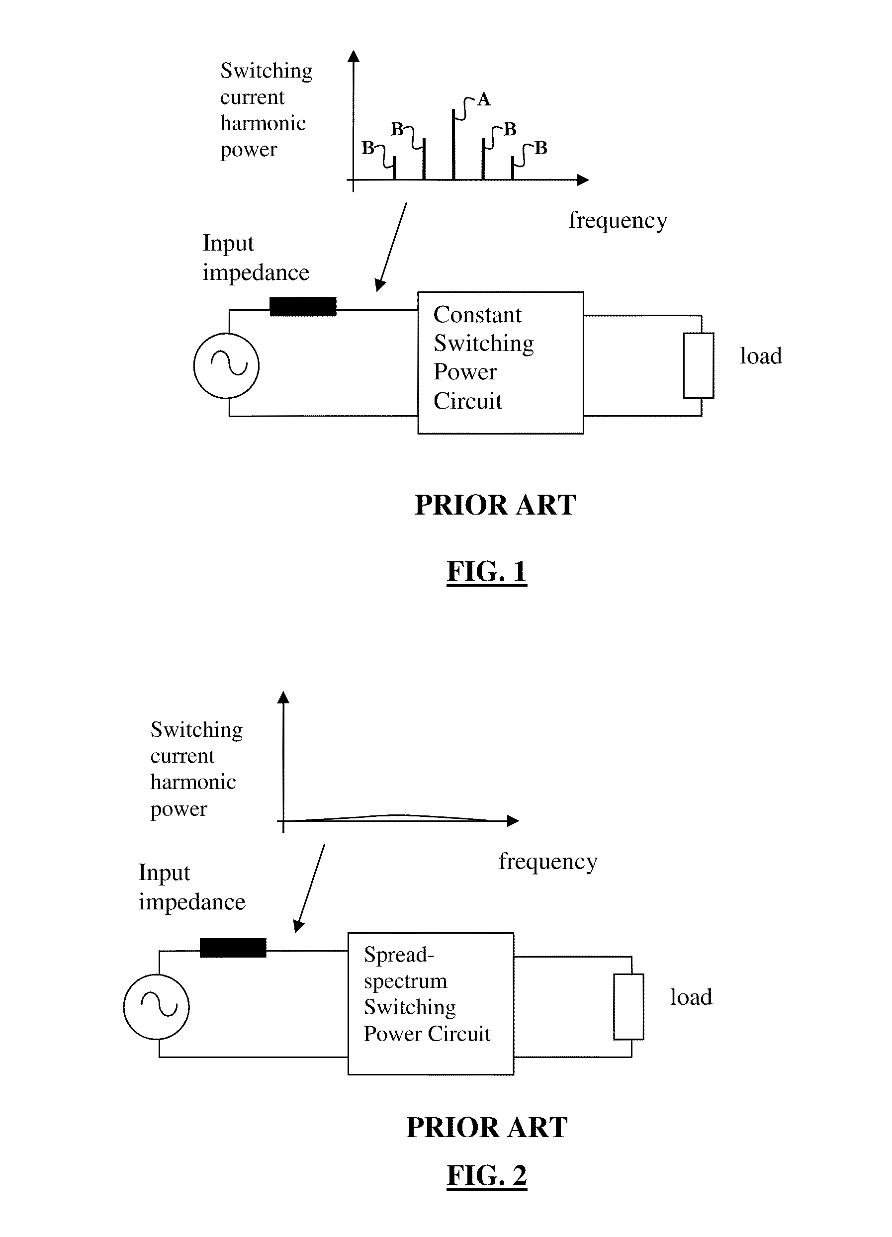
[0038]The spread-spectrum technique reduces or minimizes at least one of: the concentration of the interference signals; the magnitude of at least one of the interference signals; and the average power of the interference signals. In the present embodiment, the spread-spectrum technique minimizes all three of these aspects, and in particular, the concentration, the magnitude, and the average power of all of the interference signals 5.

[0039]The spread-spectrum technique also reduces or minimizes interference within the power transfer device 1.

[0040]The spread-spectrum technique varies the transfer frequency 4 within a transfer bandwidth 6 that m...


PUM


Abstract

The present invention provides a power transfer device for charging a wireless communication device having a communication bandwidth, and an associated method of transferring power. The device and method of the invention use a spread-spectrum technique to reduce or minimize interference signals within the communication bandwidth and within the power transfer device.

Description

FIELD OF THE INVENTION[0001]The present invention relates to power transfer devices, and in particular but not limited to, power transfer devices for charging wireless communication devices. The invention will be described in the context of power transfer devices that wirelessly charge portable wireless communication devices. However, it will be appreciated that the invention is not limited to this particular use.BACKGROUND OF THE INVENTION[0002]Spread-spectrum techniques have been proposed for reducing the input switching harmonics in power supplies in order to meet the IEC electromagnetic compatibility (EMC) requirements.[0003]The constant-switching actions of power converters generate harmonics at fixed frequencies as shown in FIG. 1. IEC regulations impose limits on the current harmonic components on the input side. The harmonics generated by the constant-switching power converter cause “conducted” electromagnetic interference (EMI) because the current harmonics can adversely af...

Claims


Application Information

Patent Timeline
IPC IPC(8): H02J7/00H02J17/00
CPCH02J17/00H02J7/00H02J50/12H02J50/40H02J50/70H02J50/10
Inventor HUI, SHU YUEN RONXUE, QUANWAN, KWUN CHIU
Owner CONVENIENTPOWER HK
Why Eureka
Try Eureka