Method of processing encoder signals

a technology of encoder signal and encoder, applied in the field of encoder signal processing methods, can solve the problems of slowing down the rate at which the velocity measurement is updated, and achieve the effects of reducing the length of the magnet, increasing the resolution, and increasing the resolution

Active Publication Date: 2011-08-04
TRW LIMITED
View PDF4 Cites 58 Cited by
  • Summary
  • Abstract
  • Description
  • Claims
  • Application Information

AI Technical Summary

Benefits of technology

[0007]In order to increase the resolution the magnet length can be reduced. For example, spacing 360 magnets around a track (one per 1 degree arc of track) gives ten times the resolution of 36 magnets spaced around the track. An alternative solution that has been proposed is to provide two tracks of magnetic elements, one next to the other. In the case of an angular position encoder this will comprise two annular tracks with one inside the other, both arranged about a common axis of rotation. By providing two detectors, each working from a different track, a higher resolution can be obtained than would be possible for one track.
[0009]The applicants have appreciated that in some cases the magnets on one track may interfere with the flux from the magnets on the other track, distorting the signals output from the detector. The present invention aims to provide a robust method of determining angular position which ameliorates such possible problems.
[0020]The method may therefore use 2, 3 or 4 or more usable pairs to determine velocity, building an average by combining the total time between transitions of the pairs with same multiple of the spacing between the detectors. This provides some averaging which may help to compensate for noise on the signals or jitter (for digital signals).
[0025]The method may be repeated until an angular error has been obtained for every magnet to magnet edge (the edges being the parts which cause the transitions) spaced around the track. This will give a more accurate position measurement relative to the other transitions.
[0033]Where the encoder comprises two tracks, the patterns formed by the tracks repeating periodically around the encoder, the table size can be reduced by exploiting the symmetry.
[0039]It should be understood that the invention provides maximum benefit for a magnetic encoder with more than one track because of potential interference between the tracks. However, it may also be used to improve the accuracy of other encoder types, such as an optical encoder. The method will compensate for tolerances in the encoder element sizing and positioning.

Problems solved by technology

Unfortunately, the more transitions an average is taken from, the slower the rate at which the velocity measurement is updated.

Method used


Image

  • Method of processing encoder signals
  • Method of processing encoder signals
  • Method of processing encoder signals

Examples


Embodiment Construction

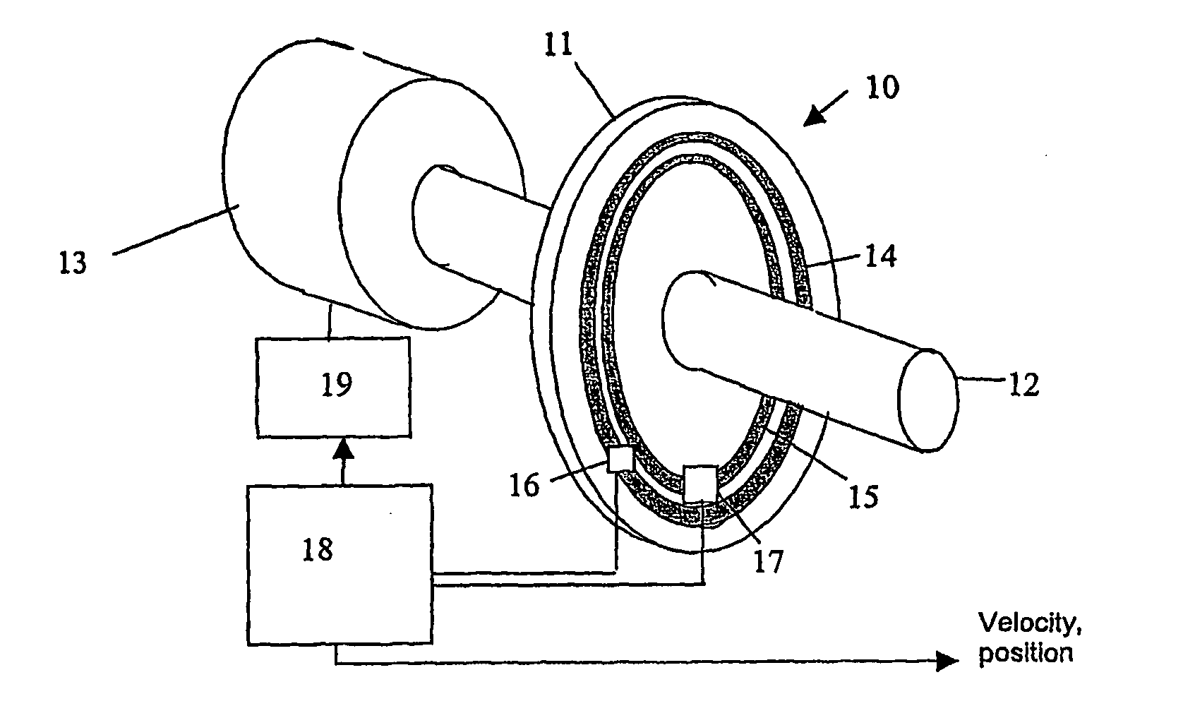
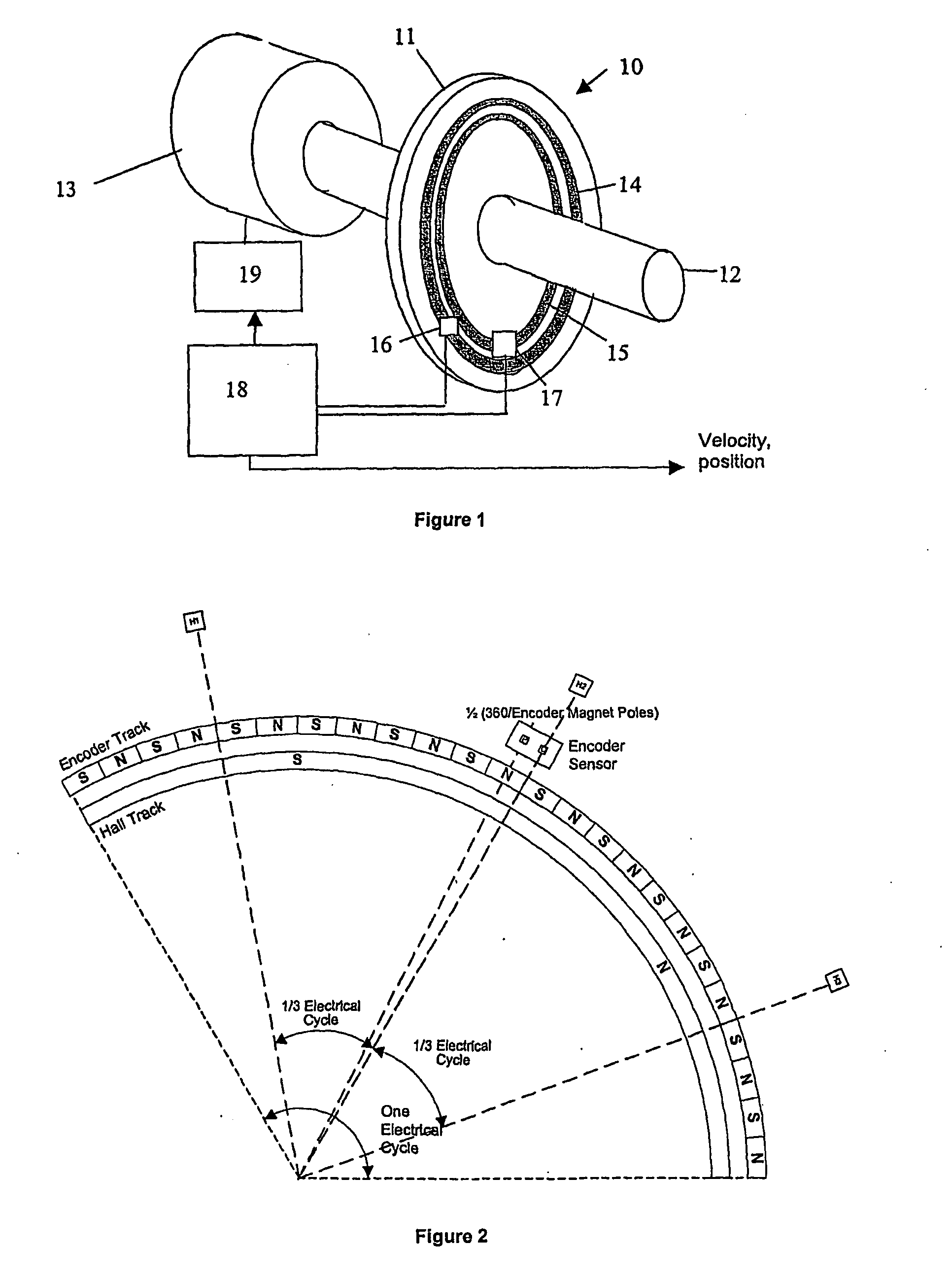
[0052]A position sensing device 10 is shown in FIG. 1. It comprises an encoder 11 attached to an output shaft 12 of a three phase electric motor 13. The device comprises an encoder disk which is secured to the shaft 12 by a set of bolts (not shown) or by welding. The disk supports two tracks 14, 15 of magnets which are arranged concentrically around the shaft axis. A first track comprises 3 pole pairs of magnets, each pair occupying an arc of 120 degrees mechanical with the second track comprising 36 pole pairs of magnets arranged in 3 sets of 24, each set of 24 occupying the same angular region as one pole pair of magnets of the first track.

[0053]Secured to a fixing bracket alongside the encoder disk is a pcb that carries two sets of detectors 16, 17. The first 17 of these is a set of Hall effect sensors. These are aligned such that they detect the passing of the magnets of the first track. The output of the Hall sensors, which will comprise a 3 bit (8 value) code is passed to a mo...


PUM


Abstract

A method of processing signals in a rotary encoder of the kind which comprises at least one annular track of encoding regions arranged as an alternating pattern of first encoding regions and second encoding regions, comprises providing a first detector at a first fixed position which is arranged to produce a first alternating output signal as the track of encoding regions rotates about its axis past the detector, the alternating signal comprising a series of transitions between a first state corresponding to the detector being aligned with a first encoding region and a second state corresponding to the detector being aligned with second encoding region;providing a second detector at a second fixed position which is arranged to produce a first alternating output signal as the track of encoding regions rotates about its axis past the detector, the alternating signal comprising a series of transitions between a first state corresponding to the detector being aligned with a first encoding region and a second state corresponding to the detector being aligned with second encoding region;identifying a usable pair of transitions in the first and second signals comprising a transition of the first signal from the first state to the second state followed by a transition in the second signal from the first state to the second state without in the intervening period having changed from the second state to the first state; measuring the elapsed time between the transitions of the identified usable pair, and determining the angular velocity by combining the elapsed time with the spacing between the first and second detectors.

Description

CROSS-REFERENCE TO RELATED APPLICATIONS[0001]This application claims priority to International Patent Application No. PCT / GB2007 / 003148 filed Aug. 17, 2007, the disclosures of which are incorporated herein by reference in their entirety, and which claimed priority to Great Britain Patent Application No. 0616437.0 filed Aug. 18, 2006, the disclosures of which are incorporated herein by reference in their entirety.BACKGROUND OF THE INVENTION[0002]This invention relates to improvements in methods of processing encoder signals, and in particular to determining position and / or velocity from encoders, and in particular rotary encoders. It is especially suited to rotary encoders which include at least one track of magnetic encoding elements.[0003]It is known to provide an encoder which comprises at least one track of magnetic elements arranged in an alternating sequence of north and south poles, and a detector which produces an output signal having a first state when proximal to one of the...

Claims


Application Information

Patent Timeline
Patent Type & Authority Applications(United States)
IPC IPC(8): G01B7/30
CPCG01D5/145G01D5/24452G01D5/2448G01P3/487G01D5/2451G01P3/481G01D5/2449G01D18/001G01P3/44
Inventor DIXON, CHRISTOPHER DAVIDWILLIAMS, CONNEL BRETTREEVE, JOHN MARTINLI, JIANG
Owner TRW LIMITED
Why Eureka
Try Eureka