Method for driving electro-optic displays

a technology of electro-optic displays and displays, applied in the direction of electric digital data processing, instruments, computing, etc., can solve the problems of inadequate service life of these displays, preventing their widespread use, and gas-based electrophoretic media being susceptible to the same types of problems

Active Publication Date: 2011-08-04
E INK CORPORATION
View PDF7 Cites 60 Cited by
  • Summary
  • Abstract
  • Description
  • Claims
  • Application Information

AI Technical Summary

Benefits of technology

[0030]Accordingly, this invention provides a method of driving a large area display comprising a plurality of sub-units arranged in a plurality of rows and columns, each sub-unit having an associated row driver and an associated column driver, the sub-units within each column being interconnected such that the associated column driver drives the column electrodes of all the sub-units within the column. The method comprises providing a separate chip select signal to each row of sub-units, so that only one row of sub-units is scanned at any one time, and all of the sub-units in the selected row are scanned simultaneously. The method f...

Problems solved by technology

Nevertheless, problems with the long-term image quality of these displays have prevented their widespread usage.
For example, particles that make up electrophoretic displays tend to settle, resulting in inadequate service-life for these displays.
Such gas-based electrophoretic media appear to be susceptible to the same types of problems due to particle settling as liquid-based electrophoretic media, when the media are used in an orientation which permits such settling, for example in a sign where the medium is disposed in a vertical plane.
Indeed, particle settling appears to be a more serious problem in gas-based electrophoretic media than in liquid-based ones, since the lower viscosity of gaseous suspending fluids as compared with liquid ones allows more rapid...

Method used


Image

  • Method for driving electro-optic displays
  • Method for driving electro-optic displays

Examples


Embodiment Construction

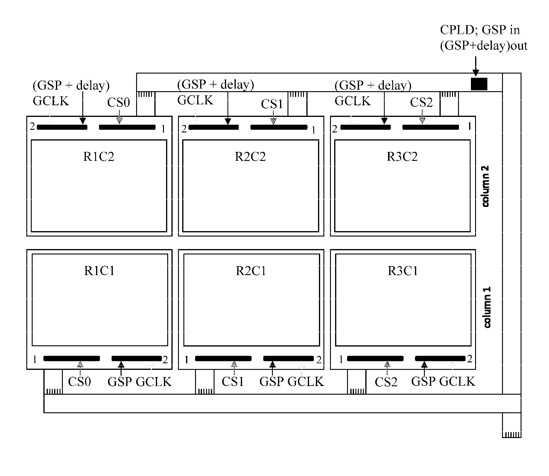
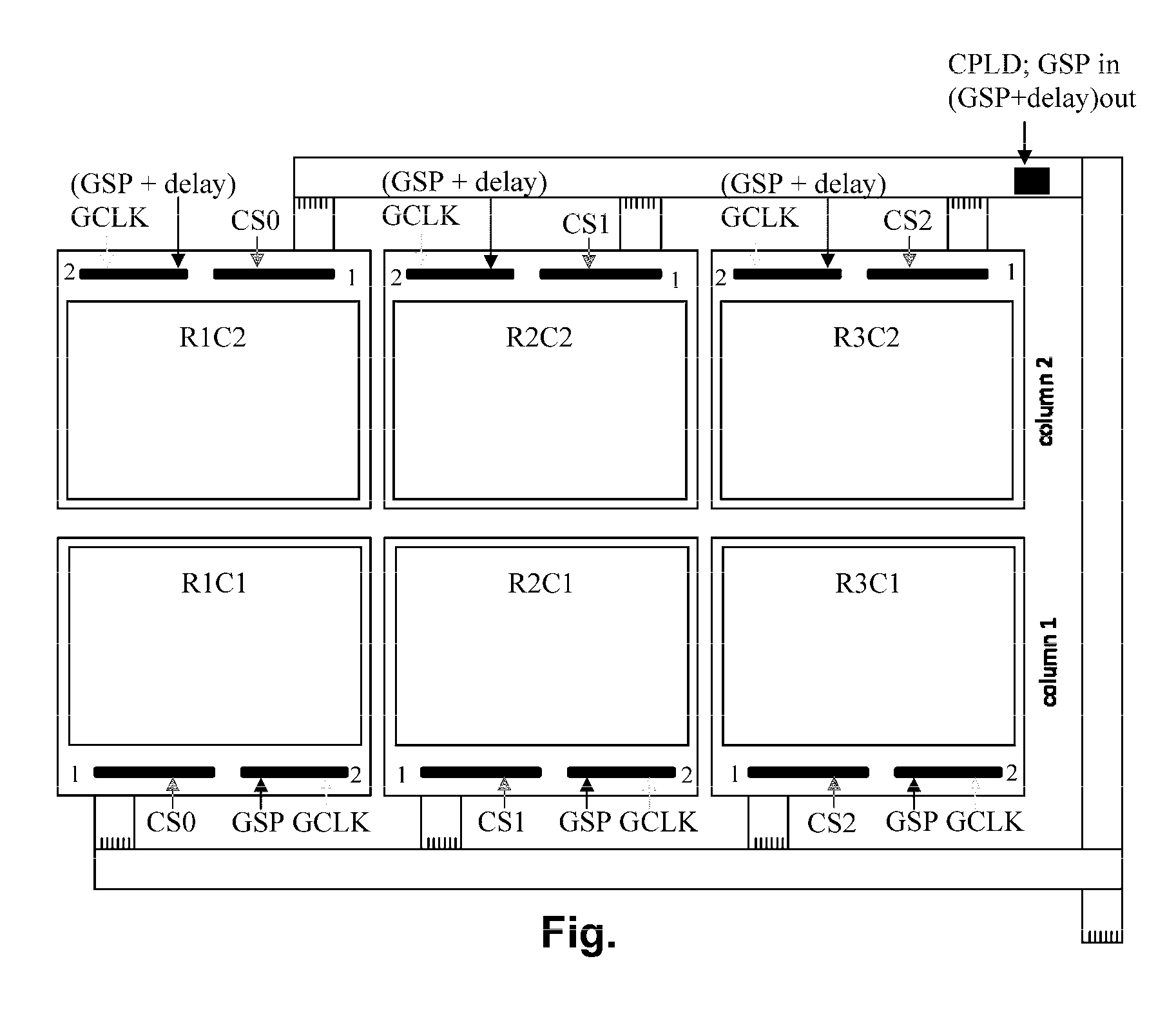
[0042]As already noted, the accompanying drawing is a schematic top plan view of a large area display of the present invention. This large area display is formed from six sub-units arranged in three rows and two columns, the individual sub-units being denoted R[ow]1C[olumn]1 etc. (The terms “rows” and “columns” are used herein not in the layman's sense of referring to horizontal and vertical lines but in the conventional manner by those skilled in the technology of active matrix electro-optic displays, i.e., “row” refers to a line of pixels or sub-units which are selected simultaneously and “column” refers to a group of pixels or sub-units interconnected by a column electrode. Thus, in the FIGURE, the rows of both pixels and sub-units are vertical as illustrated, while the columns are horizontal.) For purposes of illustration, it will be assumed that the individual sub-units have a resolution of 800 rows by 600 columns, so that the entire large area display shown in the FIGURE is an...


PUM


Abstract

A large area display comprises multiple sub-units arranged in rows and columns. Each sub-unit has associated row and column drivers, with the column driver driving the column electrodes of all the sub-units a column. A chip select means provides a separate chip select signal to each row of sub-units, so that only one row of sub-units are scanned at a time, and all the sub-units in the selected row are scanned simultaneously. Column data are supplied to the column drivers as a linear series of column data values; and delayed Gate Start Pulse signals are fed to the column drivers in each column of sub-units after the first so that these column drivers receive the delayed Gate Start Pulse signals and apply the appropriate column data values to their associated column electrodes.

Description

REFERENCE TO RELATED APPLICATIONS[0001]This application claims benefit of pending provisional Application Ser. No. 61 / 300,645, filed Feb. 2, 2010.[0002]This application is related to U.S. Pat. No. 6,252,564 and U.S. Patent Publication No. 2005 / 0253777. The entire contents of these documents, and of all other U.S. patents and published and copending applications mentioned below, are herein incorporated by reference.BACKGROUND OF INVENTION[0003]This invention relates to a method for driving electro-optic displays. More specifically, this invention relates to a method for driving large displays, especially displays which are “tiled” in the sense that the large display consists of an assembly of smaller displays (of sub-units) interconnected to function as a single large display. The term “tiled display” does not imply that all the sub-units of the large display are identical, although obviously it is often convenient to use such identical sub-units.[0004]The term “electro-optic”, as ap...

Claims


Application Information

Patent Timeline
IPC IPC(8): G09G3/34G06F3/038
CPCG09G2300/026G09G3/344G09G3/2092G09G3/3453G09G3/38G09G2310/0286G09G2310/08
Inventor BISHOP, SETH J.
Owner E INK CORPORATION
Why Eureka
Try Eureka