Video display device

a video display and display device technology, applied in the direction of color television details, instruments, color signal processing circuits, etc., can solve the problems of lack of brightness for displaying red with high saturation, and achieve the effect of convenient identification, easy setting of color adjustment parameters, and elimination of color deviation

Inactive Publication Date: 2011-08-04
SHARP KK
View PDF21 Cites 15 Cited by
  • Summary
  • Abstract
  • Description
  • Claims
  • Application Information

AI Technical Summary

Benefits of technology

[0055]This facilitates an easy identification of an origin position in the color space as a reference for calculating the correction value when correcting a signal value of an input video signal.
[0056]According to the present invention, with a color deviation occurred in a partial color region in a color reproduction range using an input video signal as it is, like in a case of conducting a video display on a wide color gamut display based on a video signal conforming to the sRGB standard, the color deviation can be eliminated by an easy setting of color adjustment parameters. While in other color regions, a video display can be conducted fully utilizing the content of an input video signal as it is. Furthermore, the present invention also enables an easy color adjustment, when a color in an arbitrary partial color region in the entire color reproduction range is required to be converted into a favorable color without a sense of discomfort.

Problems solved by technology

However, the color reproduction range CS1 of the standard color gamut display is narrow, and thus, the brightness for displaying red having a high saturation lacks.

Method used


Image

  • Video display device
  • Video display device
  • Video display device

Examples


Embodiment Construction

[0080]Further features and advantages of the present invention will become more readily apparent from the following detailed description when taken in conjunction with the accompanying drawings. Additionally, the following embodiment is merely an example of the present invention which should not limit the technical scope of the present invention.

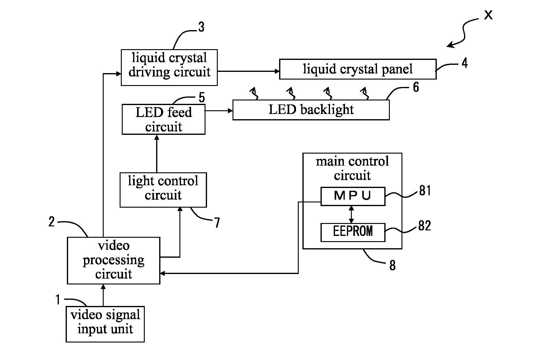
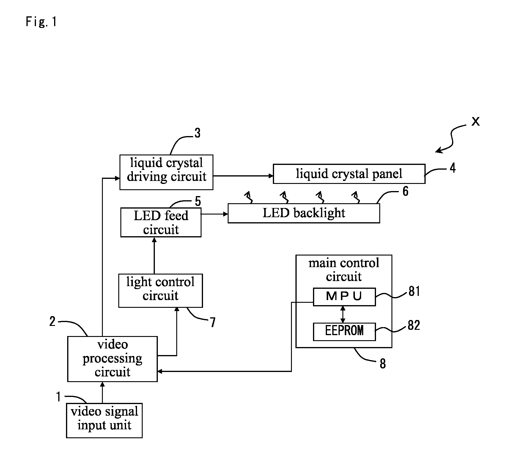
[0081]Firstly, the configuration of a liquid crystal display device X as an example of a video display device according to an embodiment of the present invention is described with reference to a block diagram shown in FIG. 1.

[0082]As can be seen from FIG. 1, the liquid crystal display device X includes a video signal input unit 1, a video processing circuit 2, a liquid crystal driving circuit 3, a liquid crystal panel 4, an LED feed circuit 5, an LED backlight 6, a light control circuit 7, and a main control circuit 8, and the like.

[0083]The LED backlight 6 having an LED as a light source illuminates the liquid crystal panel 4. The LEDs are ...


PUM


Abstract

In order to simply and easily implement an elimination of a color deviation and a color adjustment for a color correction to a favorable color in an arbitrary portion of a color region in a color reproduction range, a video processing circuit 2 corrects a luminance, a saturation and a hue of a color by the correction quantity corresponding to a reference correction coefficient with regard to a signal value of an input video signal indicating a color within a designated color region defined by a designated range of the luminance, the saturation and the hue when the color indicated by the signal value is a color in the center of the designated color region or at a core for occupying a predetermined range around the center. Otherwise, the video processing circuit 2 corrects the luminance, the saturation and the hue of the color of the signal value by the correction quantity gradually smaller as a position in a color space of the color indicated by the signal value approaches a boundary position of the designated color region.

Description

FIELD OF THE INVENTION[0001]The present invention relates to a video display device for correcting a color in an arbitrary portion of a color range in a color reproduction range of an input video signal, based on each of a luminance, a saturation, and a hue.BACKGROUND OF THE INVENTION[0002]A conventional and ordinary video display device comprises a display (hereinafter, referred to as “standard color gamut display”) displayable of a video in colors in a color reproduction range conforming to the sRGB (standard RGB) standard, a national standard of IEC (International Electrotechnical Commission). In contrast, a recent video display device, particularly a liquid crystal display device, realizes a higher quality picture, having a wider representable range of colors than the conventional device.[0003]For example, when a video signal conforming to the sRGB standard is input, and when video display is conducted by directly using the video signal, a liquid crystal display device, having; ...

Claims


Application Information

Patent Timeline
Patent Type & Authority Applications(United States)
IPC IPC(8): G09G5/02
CPCG09G3/2003G09G3/3406G09G3/3607G09G5/02G09G2320/0666H04N9/68G09G2360/16H04N1/6058H04N1/62H04N9/643G09G2340/06
Inventor KONDOH, NAOKOGOTOH, TOSHIYUKI
Owner SHARP KK
Why Eureka
Try Eureka