Interconnect for on-body analyte monitoring device

an analyte monitoring and interconnection technology, applied in the field of analyte monitoring system, can solve the problems of degrading affecting the performance of the interconnection, and affecting the durability of the pogo pin

Active Publication Date: 2011-08-04
ABBOTT DIABETES CARE INC
View PDF101 Cites 185 Cited by
  • Summary
  • Abstract
  • Description
  • Claims
  • Application Information

AI Technical Summary

Benefits of technology

[0012]In some embodiments, the elongate interconnect is coupled to the electronics unit, for example, to a circuit board disposed in the body of the electronics unit, to establish electrical communication between the electronics unit and interconnect. Additionally, the elongate interconnect can establish electrical communication with an analyte sensor. In some embodiments, the elongate interconnect can include a conductive material such as a conductive contact to contact or otherwise couple to the analyte sensor, thereby establishing electrical communication between the interconnect and the analyte sensor. In some embodiments, the elongate interconnect is formed of a flexible material such that the extended length of the interconnect can collapse or otherwise deform when the electronics unit is coupled to the analyte sensor. Upon disengagement of the analyte sensor and the electronics unit, the elongate interconnect can return to its non-collapsed configuration.

Problems solved by technology

Despite such correlation, many individuals diagnosed with a diabetic condition do not monitor their glucose levels as frequently as they should due to a combination of factors including convenience, testing discretion, pain associated with glucose testing, and cost.
However, each of these known interconnects has potential drawbacks.
For example, pogo pins are not durable and moisture can seep into the spring mechanism, thereby degrading their performance.
Similarly, polymer pins can degrade and wear after multiple cleanings Solid pins generally require extensive modification of existing systems, leading to higher costs for the patient.
Spring connections are delicate, and may be prone to failure after extended use.
In other instances, a user may need to wear an on-body analyte monitoring device for an extended period of time.
However, such devices can be bulky and uncomfortable due to the size and vertical height (“Z-height”) of the electronics unit and the size of the mounting unit, which is should be sufficiently large to house the electronics unit.

Method used


Image

  • Interconnect for on-body analyte monitoring device
  • Interconnect for on-body analyte monitoring device
  • Interconnect for on-body analyte monitoring device

Examples


Embodiment Construction

[0032]Before the present disclosure is described in detail, it is to be understood that this disclosure is not limited to particular embodiments described, as such may, of course, vary. It is also to be understood that the terminology used herein is for the purpose of describing particular embodiments only, and is not intended to be limiting, since the scope of the present disclosure will be limited only by the appended claims.

[0033]Where a range of values is provided, it is understood that each intervening value, to the tenth of the unit of the lower limit unless the context clearly dictates otherwise, between the upper and lower limit of that range and any other stated or intervening value in that stated range, is encompassed within the disclosure. The upper and lower limits of these smaller ranges may independently be included in the smaller ranges is also encompassed within the disclosure, subject to any specifically excluded limit in the stated range. Where the stated range inc...


PUM


Abstract

Disclosed herein are systems and methods for providing a compressible interconnect for allowing electrical communication between an electronics unit and an analyte sensor in an on-body analyte monitoring device. In other embodiments, systems and methods are provided for reducing the Z-height of an on-body analyte monitoring device by utilizing novel interconnects.

Description

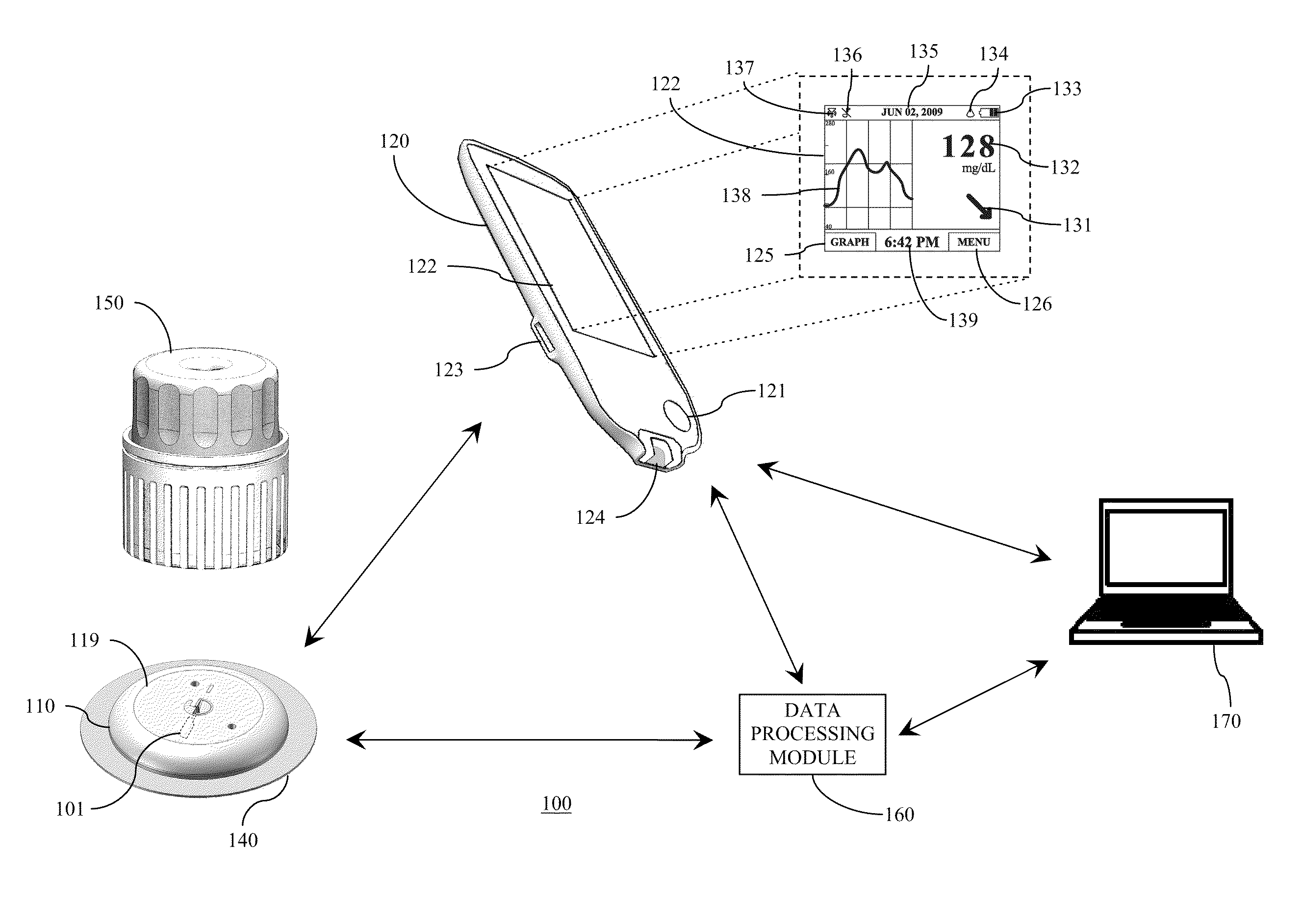
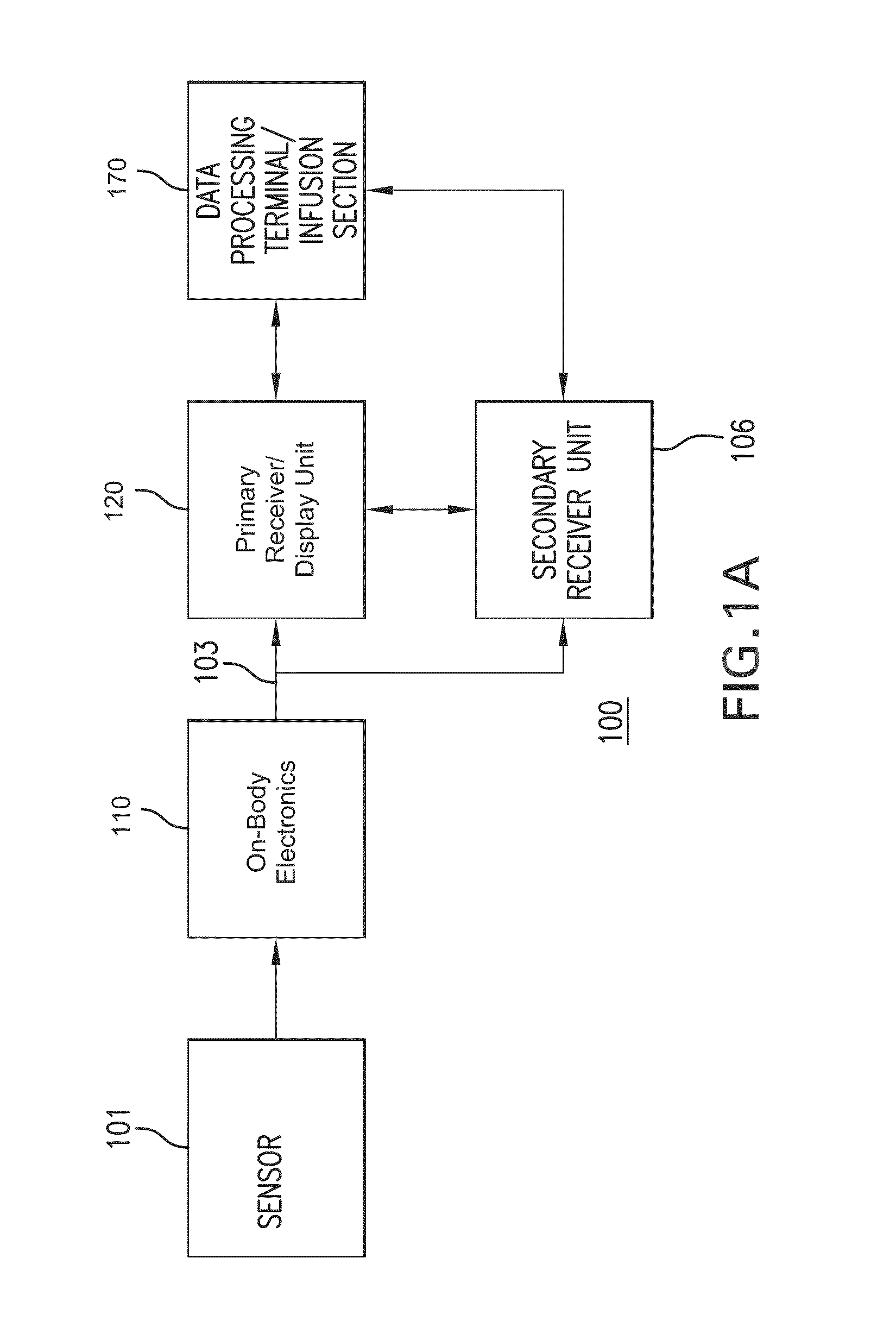
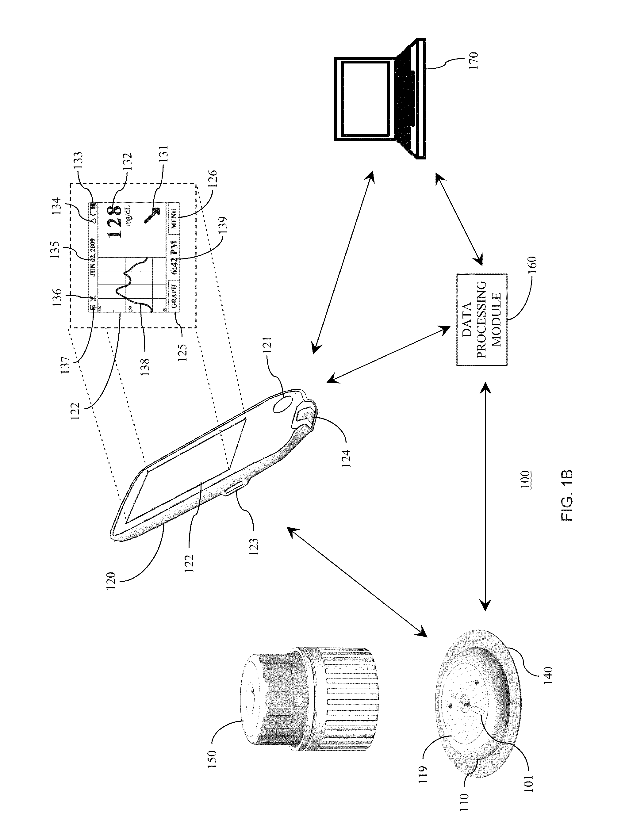
RELATED APPLICATIONS[0001]The present application claims the benefit of U.S. Provisional Application No. 61 / 247,516, filed Sep. 30, 2009, the disclosure of which is incorporated herein by reference for all purposes.FIELD OF THE INVENTION[0002]The present invention relates to an analyte monitoring system. More particularly, the present invention relates to apparatus for establishing electrical communication between an analyte sensor and an electronics unit in an on-body analyte monitoring device.BACKGROUND OF THE INVENTION[0003]The detection and / or monitoring of glucose levels or other analytes, such as lactate, oxygen, A1C, or the like, in certain individuals is vitally important to their health. For example, the monitoring of glucose is particularly important to individuals with diabetes. Diabetics generally monitor glucose levels to determine if their glucose levels are being maintained within a clinically safe range, and may also use this information to determine if and / or when i...

Claims


Application Information

Patent Timeline
Patent Type & Authority Applications(United States)
IPC IPC(8): G06F19/00G01R1/20
CPCA61B5/0002A61B5/14532A61B2562/227A61B2560/0412A61B2560/0443A61B5/742H04L67/12C12Q1/006A61B5/14865A61B5/14542A61B5/14546A61B5/1477A61B5/743A61B2562/164A61B2562/222
Inventor STAFFORD, GARY A.
Owner ABBOTT DIABETES CARE INC
Why Eureka
Try Eureka