
System for Concealed Fastening of Building Finishing Elements

a technology for finishing elements and concealed fastening, which is applied in the direction of building repairs, walls, covering/linings, etc., can solve the problems of increasing installation costs, exposing edges and underlying structures, and adding additional steps. , to achieve the effect of minimum additional skills and minimal implementation costs

Active Publication Date: 2011-08-11
JAMES HARDIE TECH LTD
View PDF10 Cites 3 Cited by
  • Summary
  • Abstract
  • Description
  • Claims
  • Application Information

AI Technical Summary

Benefits of technology

[0012]According to another aspect of the invention, there is provided a concealed building finishing element system including a building finishing element having a structure-facing surface and an exterior-facing surface; and at least one load-bearing concealed building finishing element fixing tab, the tab including a first portion and a second portion, the first portion being adapted for connection to a structure-facing surface of a building finishing element such that said second portion of said tab extends outwardly from said building finishing element, and said second portion being adapted for connection to a support structure thereby to secure a portion of said building finishing element to said support structure whereby the connection between said first portion of said tab and said structure-facing surface of said building finishing element is substantially concealed from an outwardly directed exterior-facing surface of said building finishing element, the tab being configured so as to support said portion of the building finishing element and retain it in a fixed position.
[0013]According to another aspect of the invention, there is provided a method of securing a building finishing element to a support structure, said method including the steps of selecting one or more load bearing concealed building finishing element fixing tabs, each tab including a first portion and a second portion, connecting said first portion of the tab to a structure-facing surface of the building finishing element such that the second portion extends outwardly from the building finishing element, and connecting the second portion of the tab to a support structure to thereby secure the building finishing element to the support structure whereby the connection between the first portion of the tab and said structure facing surface of the building finishing element is concealed from an outwardly directed exterior facing surface of said building finishing element, the tab or tabs being configured to support the building finishing element and retain it in a fixed position.
[0021]In accordance with one preferred embodiment of the invention, the first and / or second portions of the tab include one or more pre-formed fastener receiving perforations or areas directed to receive the fasteners, thereby enabling use of a harder, and, possibly structurally more rigid material, which in turn may facilitate use of thinner sectioned tabs which will allow the trim to sit closer for a more flush mounting to the supporting structure.
[0024]Additionally, the use of perforations advantageously assists with positioning the tabs relative to the trim members and the underlying structure and / or may provide a guide to appropriate fastener spacing and positioning relative to the tab boundaries. The perforations can be sized and located as necessary depending on the size and weight of the trim member, the number of fasteners required for the forces acting on the load-bearing tab, ease of installation, and for aesthetic reasons.
[0028]The invention advantageously allows the use of standard fastening guns and standard commercially available fasteners. This advantageously results in minimum cost of implementation and minimum additional skills required for installers. These advantages are further enhanced when the tabs include indicia in the form of fastening guides.
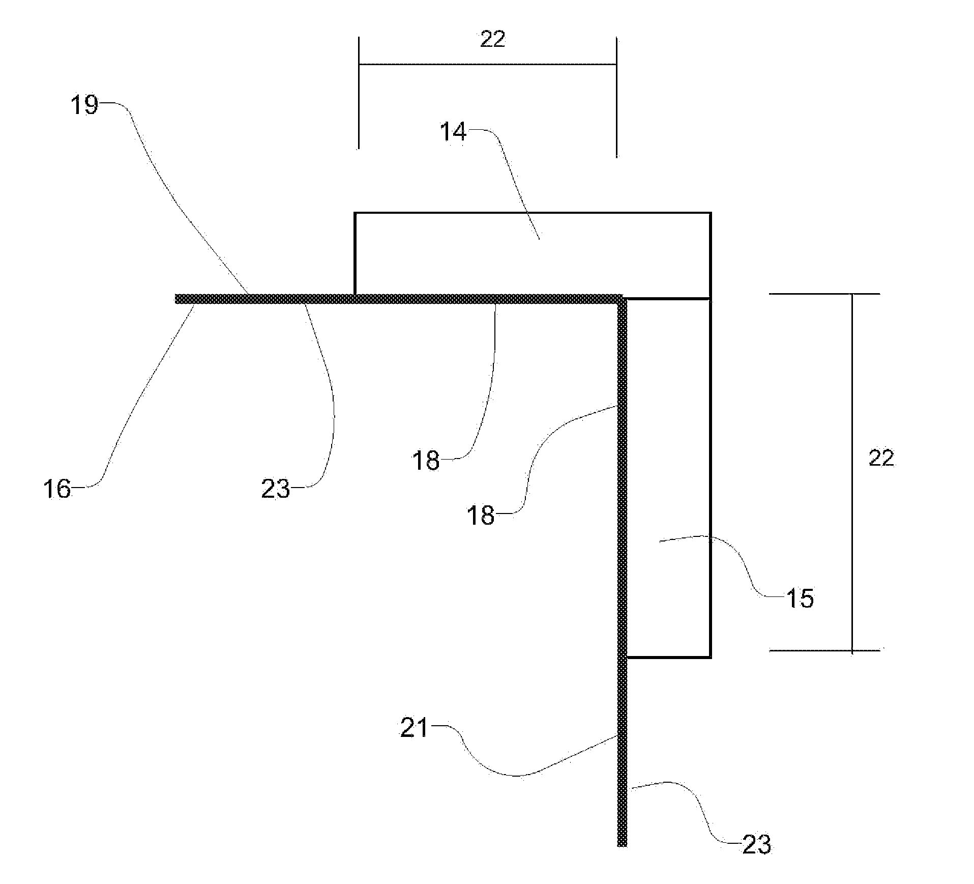
[0029]Preferably, the load-bearing tabs are discrete tabs. Advantageously, tabs are able to be connected to any position on the structure facing surface of the trim member. This provides flexibility of positioning the tabs to suit various installation requirements and work around various obstructions, etc. The width of each tab is preferably smaller than the edge dimensions of the building finishing element to which it is connected. In this regard, the width is preferably selected such that when a tab is secured to the end of a first building finishing element which is to abut with an adjacent second building finishing element, such as happens with trim at the corners of openings and the like, there is room for the second trim member to sit over the second portion of the tab securing the adjacent end of the first trim member, without the first portion of the tab on the second trim member overlapping with the second portion of the first trim member.

Problems solved by technology

However, any building movements tended to cause the mitre joints to open up which as well as being unsightly, exposed the edges and the underlying structure to the weather.
It will be appreciated that these additional steps are time consuming and add additional cost to the installation.
While the reinforcing provided by the backing member provides resistance to cracking of the cementitious layer, it is also likely to increase the overall weight and cost of the trim piece.
Additionally, manufacture of the integrated product is likely to be more complex than the manufacture of a simple discrete trim piece suitable for nail or screw fixing, as described above.
Furthermore, this sheathing product is likely to have limited installation flexibility, in particular relating to ease of positioning the product in situ due to the nailing flange extending along the entire length of the trim piece.
Furthermore, the described trim piece is necessarily provided as a pre-fabricated product and can only be used on corners limiting the flexibility on window and door trim installation.
Similar issues arise with the installation of other standard building finishing elements such as fascia boards, band boards, soffits and the like, in that face fixing through the element complicates the finishing process by requiring touch up painting or the use of prefinished or capped fasteners or the like.

Method used


Image

  • System for Concealed Fastening of Building Finishing Elements
  • System for Concealed Fastening of Building Finishing Elements
  • System for Concealed Fastening of Building Finishing Elements

Examples


Embodiment Construction

[0051]In the description which follows like parts are marked throughout the specification and drawings with the same reference numerals, respectively. The drawings figures may not necessary be to scale and certain elements may be shown in generalized or somewhat schematic form in the interest of clarity and conciseness.

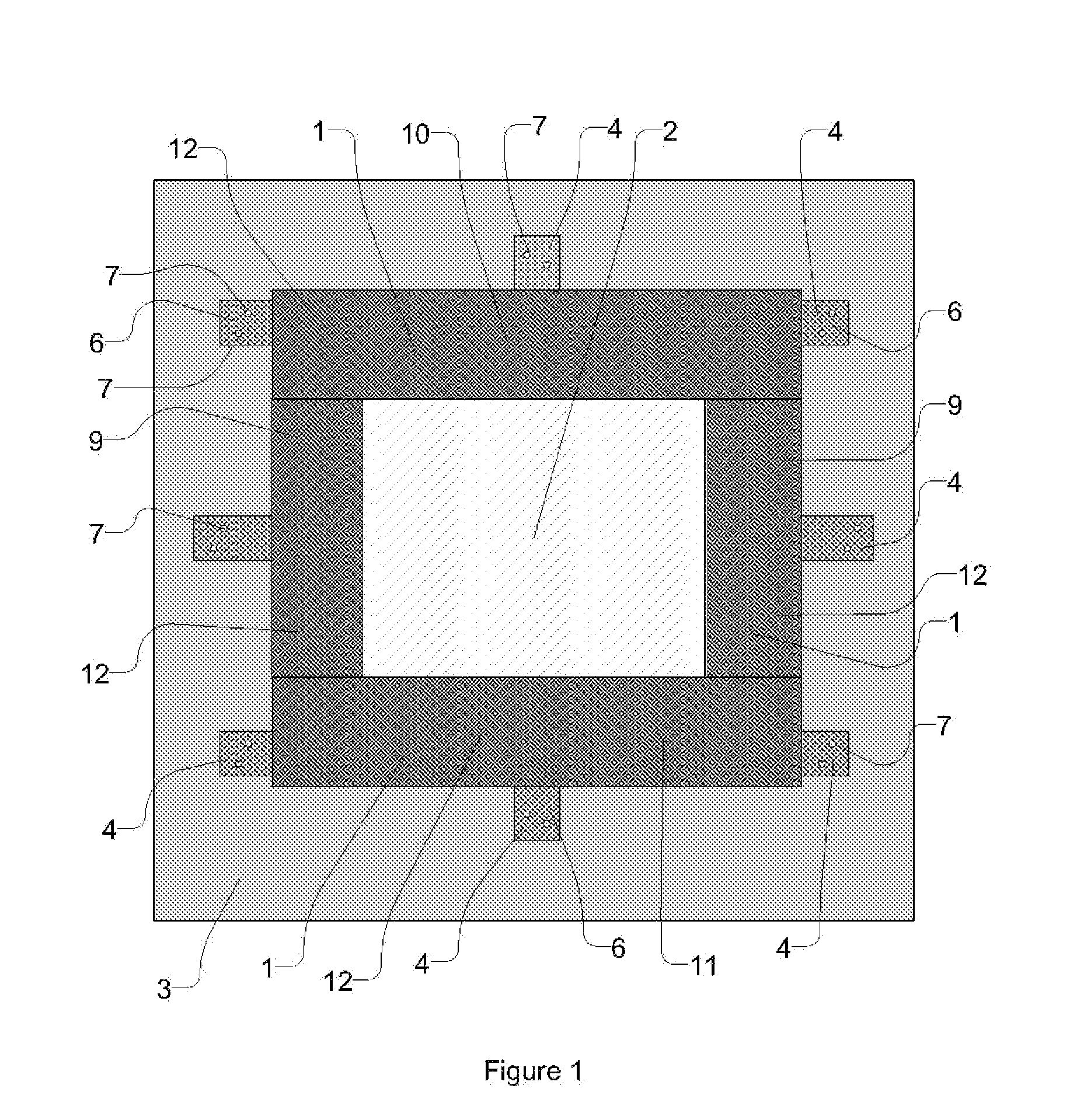
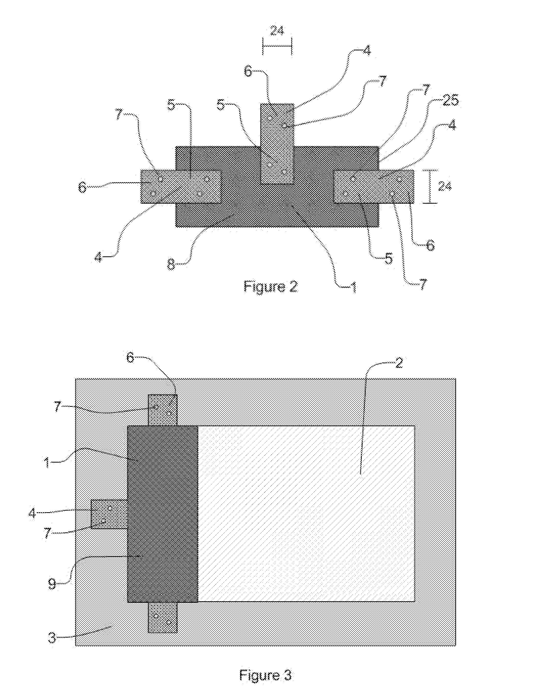
[0052]Referring to FIGS. 1 and 2 of the drawings, a system according to one embodiment of the invention is illustrated in the form of window trim installation which includes a plurality of building finishing elements in the form of trim members 1, each affixed around a window 2 to the underlying exterior structure of the building 3 by three rigid load bearing tabs 4.

[0053]Each load bearing tab 4 includes a first portion 5 and a second portion 6, each portion, optionally, having a number of perforations 7. The tab 4 may be, for example, nailed, stapled, or screwed to a structure-facing surface 8 of each trim member 1 through one or more of the optional perforations 7 i...


PUM


Abstract

In one form of building structure, trim installations are applied around window or door frame openings and at internal or external corners of a building. The trim serves both an aesthetic purpose in adding a decorative feature to building envelopes and also adds an additional weatherproofing purpose in allowing for more complete weatherproofing of building envelope corners and openings. The present invention relates to a concealed fastening building finishing element system that enables concealed fastening of finishing elements such as trim components, fascia boards, frieze boards, belly band boards, and the like to an underlying structure and to the fixings used in these systems. The invention is particularly useful with trim elements around window and door frame openings and at building corners.

Description

BACKGROUND OF THE INVENTION[0001]The present invention relates to a concealed fastening building finishing element system that enables concealed fastening of finishing elements such as trim components, fascia boards, frieze boards, belly band boards, and the like to an underlying structure and to the fixings used in these systems.[0002]The invention is particularly useful with trim elements around window and door frame openings and at building corners and will be described hereinafter with reference to these applications. It will be appreciated, however, that the invention is not limited to these particular fields of use and can be used in connection with other building finishing elements where concealed fastening is desired, including but not limited to, band board features, fascia boards, soffits and the like.[0003]Any discussion of the prior art throughout the specification should in no way be considered as an admission that such prior art is widely known or forms part of the com...

Claims


Application Information

Patent Timeline
Patent Type & Authority Applications(United States)
IPC IPC(8): E04B1/38E04F13/073
CPCE04F19/0495E04F13/141
Inventor COTTIER, JOHN SYDNEYO'LEARY, KEVIN
Owner JAMES HARDIE TECH LTD
Learn More