
Touch sensing system, capacitance sensing circuit and capacitance sensing method thereof

a sensing circuit and capacitance technology, applied in the direction of resistance/reactance/impedence, instruments, measurement devices, etc., can solve the problem of ineffective enhancement of the signal-to-noise ratio (snr) of the one-end sensing circuit, and the inconvenience of using the conventional input interface including the keyboard and the mouse, so as to achieve the effect of effective enhancement of the snr

Active Publication Date: 2011-08-11
NOVATEK MICROELECTRONICS CORP
View PDF5 Cites 24 Cited by
  • Summary
  • Abstract
  • Description
  • Claims
  • Application Information

AI Technical Summary

Benefits of technology

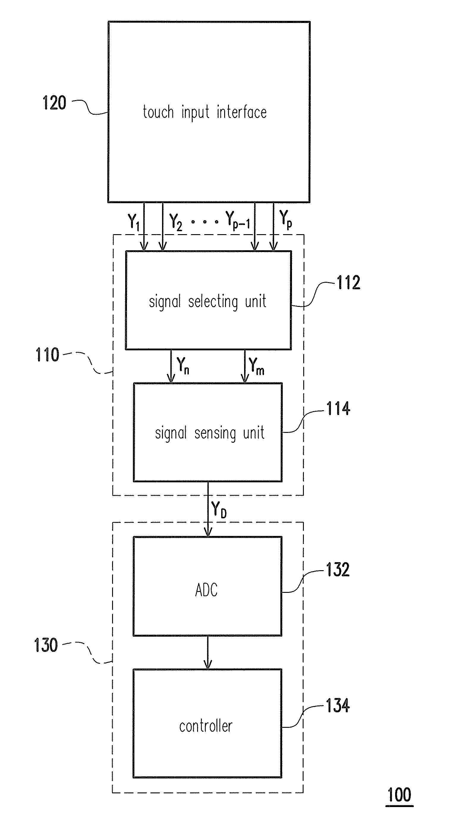
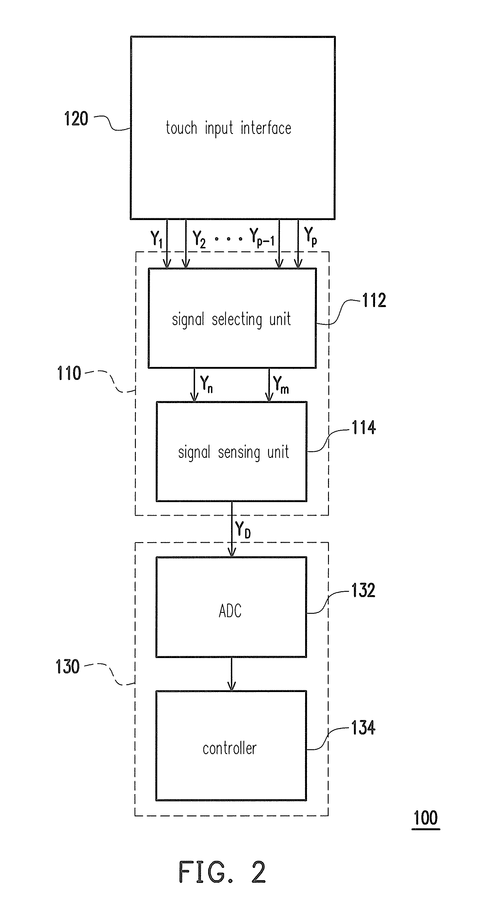
[0010]An embodiment of the invention provides a capacitance sensing circuit capable of effectively enhancing SNR thereof and achieving the purpose of power-saving by dual edge couple.
[0011]An embodiment of the invention provides a touch sensing system capable of effectively enhancing SNR of the capacitance sensing circuit thereof and achieving the purpose of power-saving by dual edge couple.
[0012]An embodiment of the invention provides a capacitance sensing method capable of effectively enhancing SNR of the capacitance sensing circuit using the same and achieving the purpose of power-saving by dual edge couple.
[0033]Based on the above, in the embodiments of the invention, by using the reference signal as a reference value for measuring the signal under test, the capacitance sensing circuit can cancel the external noise and further enhance the SNR thereof. Furthermore, in the sensing period, the capacitance sensing circuit senses the waveform under test and the reference waveform and outputs the differential signal according to the positive edge difference and the negative edge difference between the waveform under test and the reference waveform, so as to reduce the number of driving pulses of the capacitance sensing circuit and further achieve the purpose of power-saving.

Problems solved by technology

From the user's aspect, it is sometimes rather inconvenient to use the conventional input interface including the keyboard and the mouse.
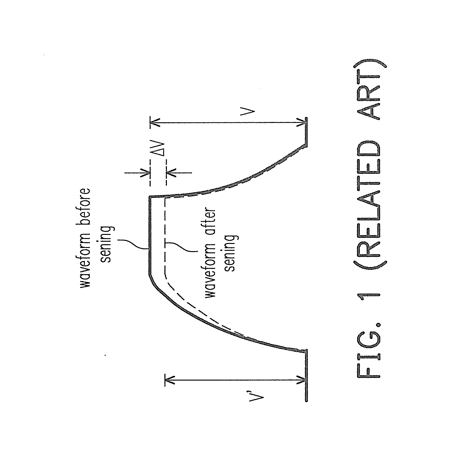
Furthermore, the reference capacitance of the capacitor under test of the one-end sensing circuit is a fixed value, and therefore the external noise can not be canceled indeed, such that signal-to-noise ratio (SNR) of the one-end sensing circuit can not be enhanced effectively.

Method used


Image

  • Touch sensing system, capacitance sensing circuit and capacitance sensing method thereof
  • Touch sensing system, capacitance sensing circuit and capacitance sensing method thereof
  • Touch sensing system, capacitance sensing circuit and capacitance sensing method thereof

Examples


Embodiment Construction

[0047]In a capacitive touch input interface, capacitance of a sensing capacitor is determined on whether a position of the sensing capacitor correspondingly on the touch input interface is touched. When the position of the sensing capacitor correspondingly on the touch input interface is touched, capacitance variation is induced by the touch object accordingly, such that a capacitance under test is generated by the touch object and the sensing capacitor.

[0048]According to the embodiments of the invention, except for the aforesaid capacitance under test, other capacitances of sensing capacitors can serve as reference values for measuring the capacitance under test. Hence, after the capacitance under test and the reference capacitance are compared, the touch position of the touch object correspondingly on the touch input interface can be determined.

[0049]In the embodiments provided hereinafter, a touch panel exemplarily acts as the touch input interface, while people having ordinary s...


PUM


Abstract

A touch sensing system which includes a touch input interface and a capacitance sensing circuit is provided. The touch input interface includes a plurality of sensing capacitors which output at least one waveform under test and at least one reference waveform. The capacitance sensing circuit includes a difference comparing unit. The difference comparing unit receives the waveform under test and the reference waveform and outputs a differential signal according to at least one positive edge difference and at least one negative edge difference between the waveform under test and the reference waveform. Furthermore, a capacitance sensing method is also provided.

Description

CROSS-REFERENCE TO RELATED APPLICATION[0001]This application claims the priority benefit of Taiwan application serial no. 99103790, filed on Feb. 8, 2010. The entirety of the above-mentioned patent application is hereby incorporated by reference herein and made a part of specification.BACKGROUND OF THE INVENTION[0002]1. Field of the Invention[0003]The invention relates to a sensing circuit and a sensing method thereof, and more particularly, to a capacitance sensing circuit and a capacitance sensing method thereof.[0004]2. Description of Related Art[0005]In this information era, reliance on electronic products is increasing day by day. The electronic products including notebook computers, mobile phones, personal digital assistants (PDAs), digital walkmans, and so on are indispensable in our daily lives. Each of the aforesaid electronic products has an input interface for a user to input his or her command, such that an internal system of each of the electronic product spontaneously ...

Claims


Application Information

Patent Timeline
Patent Type & Authority Applications(United States)
IPC IPC(8): G01R27/26
CPCG06F3/044G06F3/0446
Inventor LIN, CHING-CHUNTANG, WING-KAIHUNG, CHING-HOCHANG, TSEN-WEILIN, YI-LIANGTSAI, JIUN-JIE
Owner NOVATEK MICROELECTRONICS CORP
Learn More