Liquid crystal display device

a liquid crystal display and display area technology, applied in static indicating devices, non-linear optics, instruments, etc., can solve the problem of people's face looking unnaturally white overall, and achieve the effect of reducing the effect of whitening and reducing the decrease of the aperture ratio of the display area

Inactive Publication Date: 2011-08-11
SHARP KK
View PDF18 Cites 13 Cited by
  • Summary
  • Abstract
  • Description
  • Claims
  • Application Information

AI Technical Summary

Benefits of technology

[0035]The present invention provides a liquid crystal display device that can minimize a decrease in the aperture ratio of the display area and that can reduce the whitening phenomenon efficiently.

Problems solved by technology

It is known that the display quality achieved by a VA mode LCD when the viewer is located right in front of the screen (which will be referred to herein as “when viewed straight on”) is significantly different from the one achieved when the viewer is located obliquely with respect to the screen (which will be referred to herein as “when viewed obliquely”), which is a problem with the VA mode LCD.
However, when viewing obliquely, he or she will sense that person's face look unnaturally white overall.

Method used


Image

  • Liquid crystal display device
  • Liquid crystal display device
  • Liquid crystal display device

Examples


embodiment 1

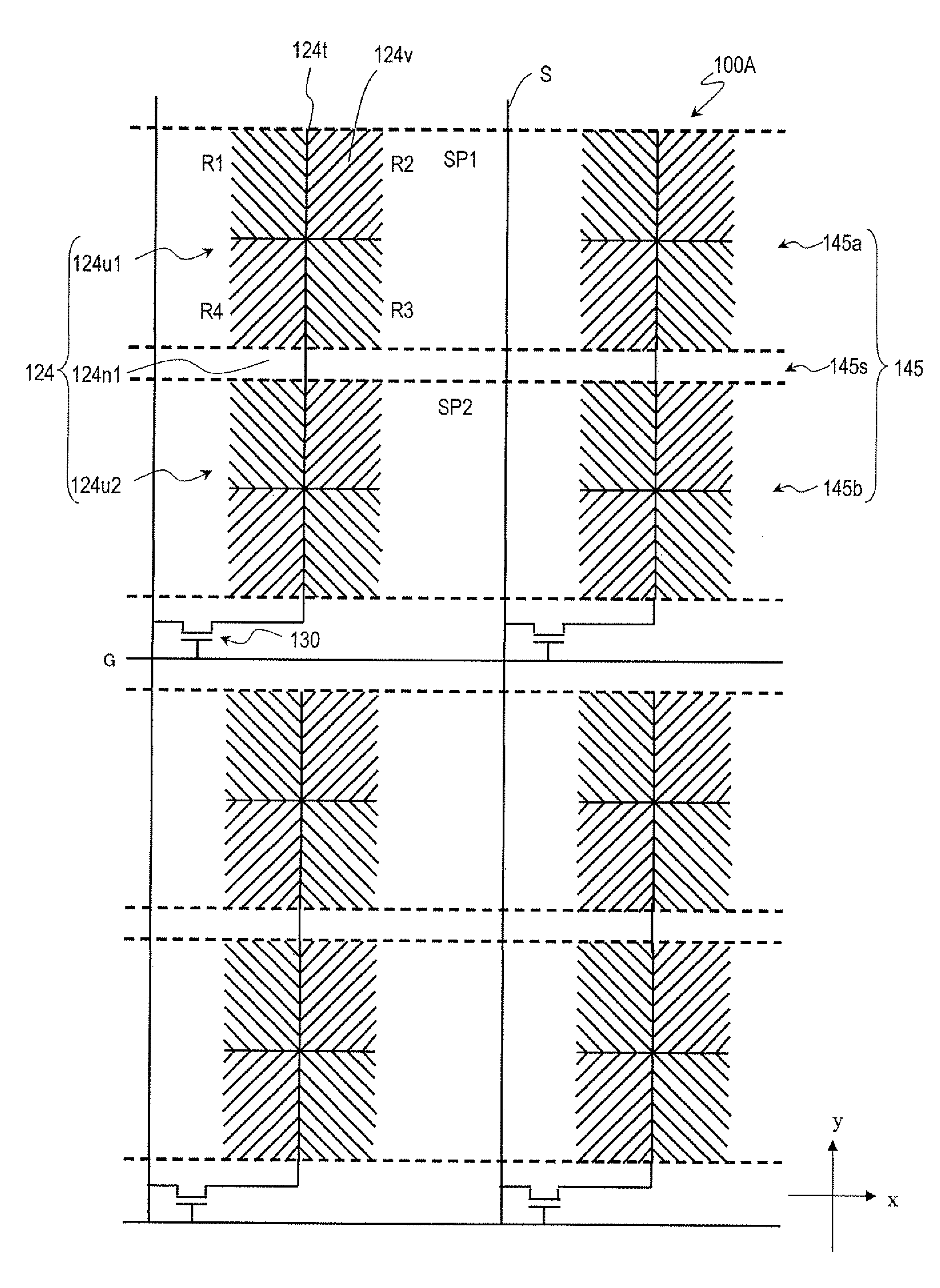
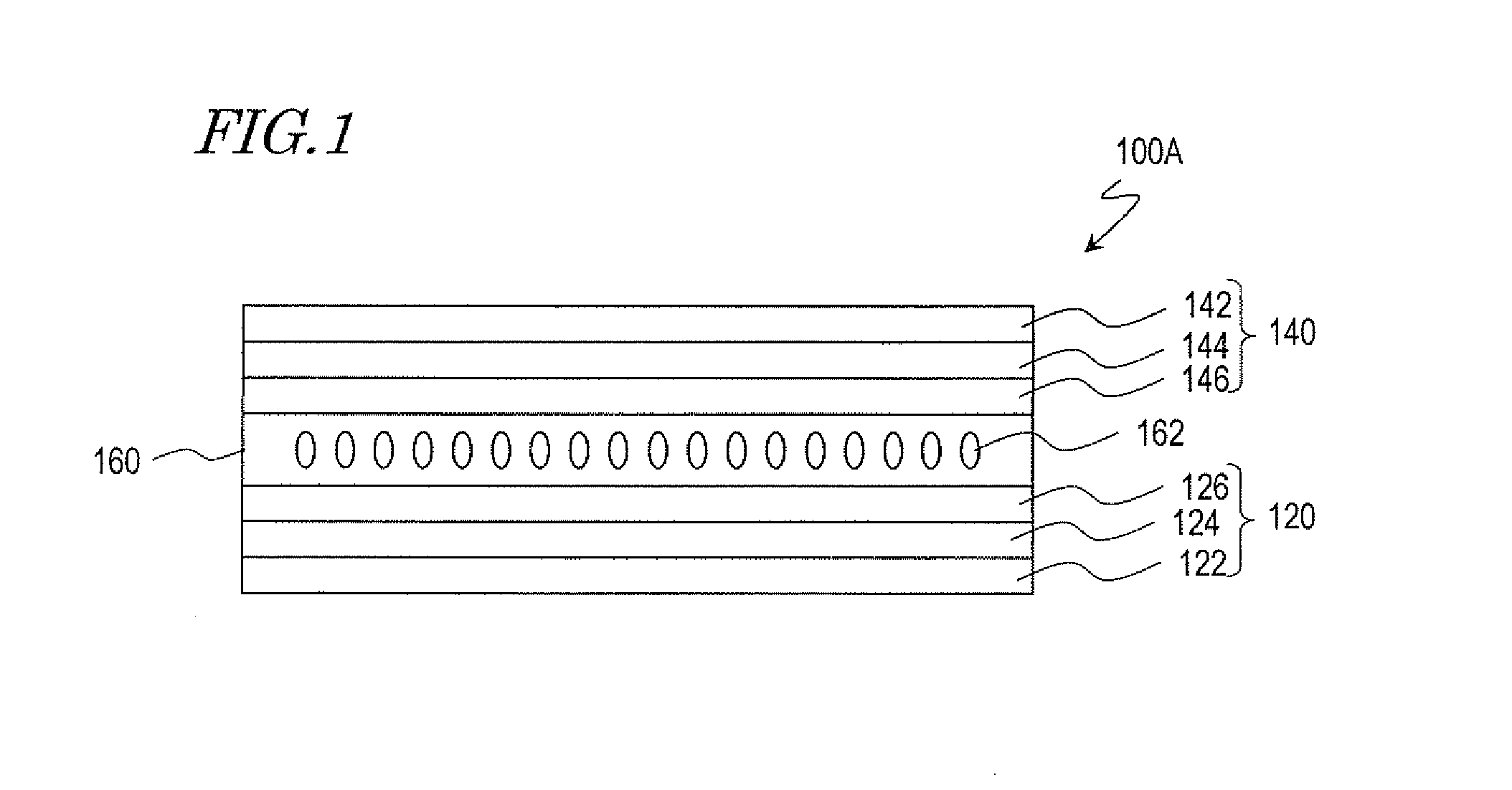
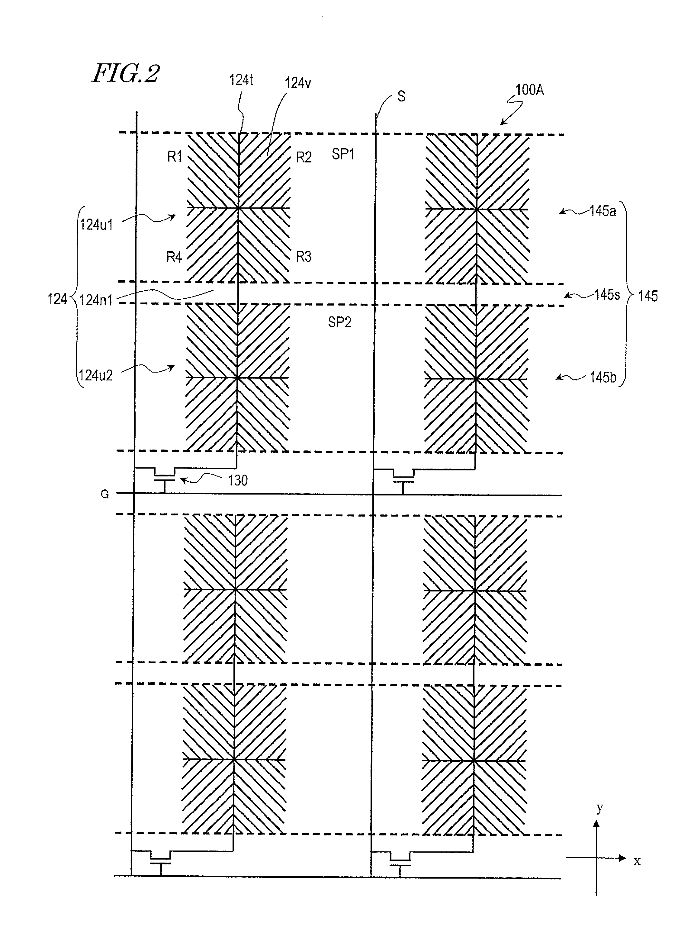
[0058]First of all, a First Specific Preferred Embodiment of a liquid crystal display device according to the present invention will be described. FIGS. 1 and 2A are respectively a schematic representation and a schematic plan view illustrating a liquid crystal display device 100A as a first preferred embodiment of the present invention.

[0059]The liquid crystal display device 100A includes an active-matrix substrate 120 with pixel electrodes 124 and an alignment layer 126 that have been stacked in this order on an insulating substrate 122, a counter substrate 140 with a counter electrode 144 and another alignment layer 146 that have also been stacked in this order on another insulating substrate 142, and a liquid crystal layer 160, which is interposed between the active-matrix substrate 120 and the counter substrate 140. Although not shown, two polarizers are provided for the active-matrix substrate 120 and the counter substrate 140, respectively, and are arranged so that their pola...

embodiment 2

[0103]Hereinafter, another preferred embodiment of a liquid crystal display device according to the present invention will be described with reference to FIG. 11. A liquid crystal display device 100B as a second preferred embodiment of the present invention has the same configuration as its counterpart of the first preferred embodiment that has already been described with reference to FIGS. 1 and 2 except that this liquid crystal display device 100B operates in the CPA mode. Thus, description of their common features will be omitted herein to avoid redundancies.

[0104]FIGS. 11(a) and 11(b) are respectively a schematic plan view and a schematic cross-sectional view illustrating the liquid crystal display device 100B. FIG. 11(b) illustrates a cross section as viewed on the plane 11b-11b′ shown in FIG. 11(a). It should be noted that the alignment layers are not illustrated in FIG. 11(b).

[0105]In the liquid crystal display device 100B, each pixel electrode 124 includes two unit portions ...

embodiment 3

[0114]In the liquid crystal display devices 100A and 100B described above, the divided counter electrodes 145 are supposed to run straight in the row direction. However, the present invention is in no way limited to those specific preferred embodiments. Optionally, each of those divided counter electrodes 145 may have a portion that is extended obliquely with respect to the row direction.

[0115]Hereinafter, a third preferred embodiment of a liquid crystal display device according to the present invention will be described with reference to FIG. 12. The liquid crystal display device 100C of this preferred embodiment has the same configuration as the liquid crystal display devices 100A and 100B described above except that the divided counter electrodes 145 of this liquid crystal display device 100C have a different shape from theirs. And description of their common features will be omitted herein to avoid redundancies. In FIG. 12, illustrated is only a portion of the counter electrode ...


PUM


Abstract

A liquid crystal display device (100) according to the present invention includes: an active-matrix substrate (120) including pixel electrodes (124); a counter substrate (140) including a counter electrode (144); and a vertical alignment liquid crystal layer (160), which is interposed between the active-matrix substrate (120) and the counter substrate (140). The counter electrode (144) includes a number of divided counter electrodes (145). Each of the pixel electrodes (124) is associated with at least two of the divided counter electrodes that are arranged over the pixel electrode (145).

Description

TECHNICAL FIELD[0001]The present invention relates to a liquid crystal display device.BACKGROUND ART[0002]Liquid crystal displays (LCDs) have been used in not only TV sets with a big screen but also small display devices such as the monitor screen of a cellphone. TN (twisted nematic) mode LCDs, which would often be used in the past, achieved relatively narrow viewing angles, but LCDs of various other modes with wider viewing angles have recently been developed one after another. Examples of those wider viewing angle modes include IPS (in-plane switching) mode and VA (vertical alignment) mode. Among those wide viewing angle modes, the VA mode is adopted in a lot of LCDs because the VA mode would achieve a sufficiently high contrast ratio.[0003]Known as a kind of VA mode LCD is an MVA (multi-domain vertical alignment) mode LCD in which multiple liquid crystal domains are defined within a single pixel region. In an MVA mode LCD, an alignment control structure is provided for at least o...

Claims


Application Information

Patent Timeline
Patent Type & Authority Applications(United States)
IPC IPC(8): G09G3/36
CPCG02F1/134309
Inventor OHGAMI, HIROYUKIHASHIMOTO, YOSHITOIYAMA, YUICHI
Owner SHARP KK
Why Eureka
Try Eureka