
Three dimensional display system

a display system and three-dimensional technology, applied in the field of three-dimensional display systems, can solve the problems of inability to adapt to dynamic scenarios, user's eyes may not be located optimally, and confuse the human visual system, so as to improve the adaptation of the system and improve the operation

Active Publication Date: 2011-08-11
LEIA INC +1
View PDF29 Cites 38 Cited by
  • Summary
  • Abstract
  • Description
  • Claims
  • Application Information

AI Technical Summary

Benefits of technology

The invention is a three-dimensional display system that aims to provide a better user experience by adapting the depth effect of the display based on the presence of users. The system uses a rendering unit to generate images for each viewing direction, and a user presence estimate to determine if a user is viewing the display. The system can switch between a three-dimensional mode and a two-dimensional mode based on the user presence estimate. The technical effect of the invention is to provide a more immersive and comfortable viewing experience for dedicated users while reducing discomfort for other viewers.

Problems solved by technology

However, as this may be considered inconvenient to the user, it is in many scenarios preferred to use auto-stereoscopic displays that use means at the display (such as lenticular lenses, or barriers) to separate views, and send them in different directions where they individually may reach the user's eyes.
However, although the described auto-stereoscopic displays provide a very advantageous three dimensional experience, they also have some associated disadvantages.
For example, auto-stereoscopic displays tend to be highly sensitive to the viewers position and therefore tend to be less suitable for dynamic scenarios wherein it cannot be guaranteed that a person is in a very specific location.
However, in some situations, the user's eyes may not be located optimally for receiving suitable image views, and therefore some auto-stereoscopic displays applications and scenarios, in particularly those where in appropriate views are directed to the eyes of the viewer, may have a tendency to confuse the human visual system leading to an uncomfortable feeling.

Method used


Image

  • Three dimensional display system
  • Three dimensional display system
  • Three dimensional display system

Examples


Embodiment Construction

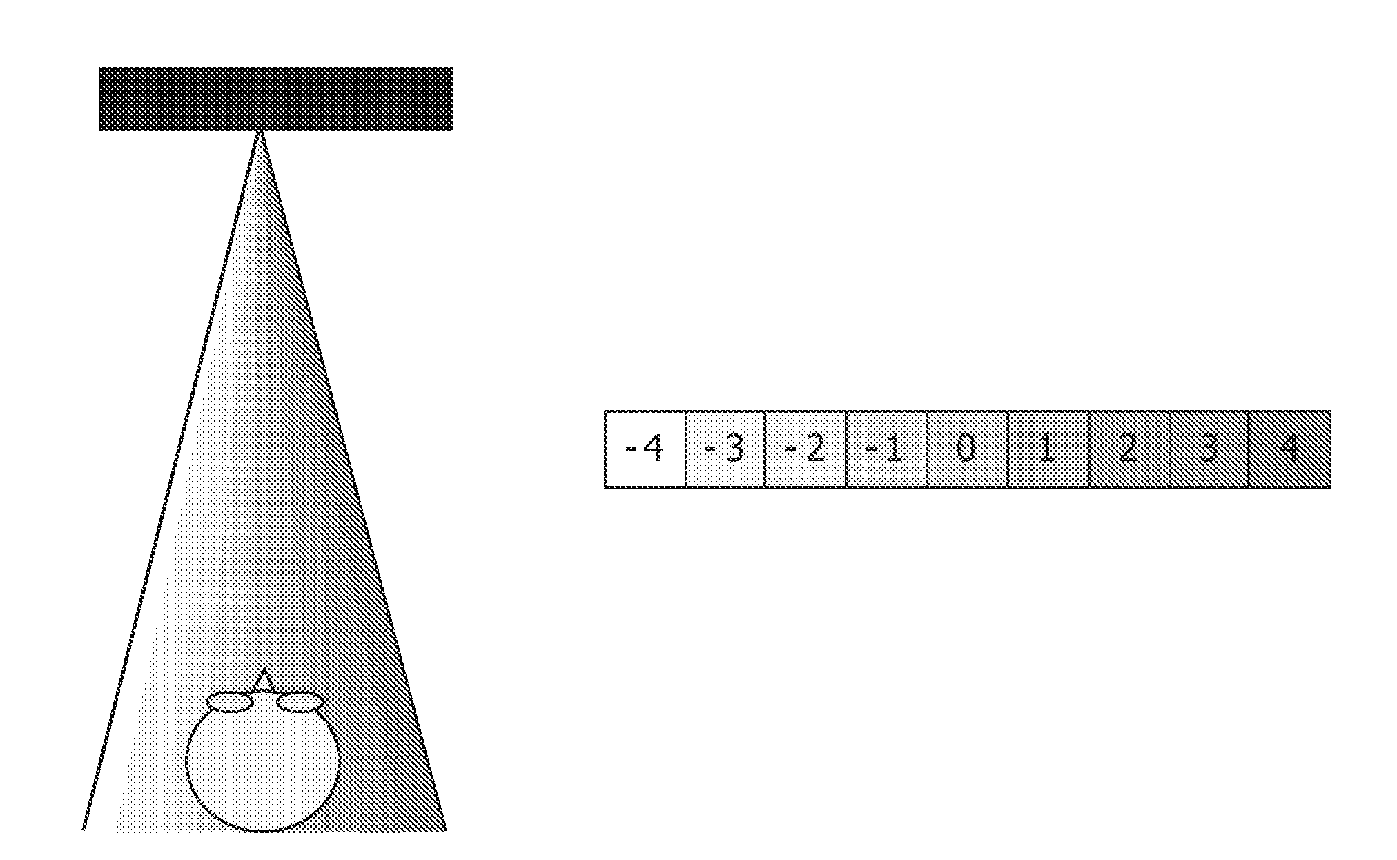
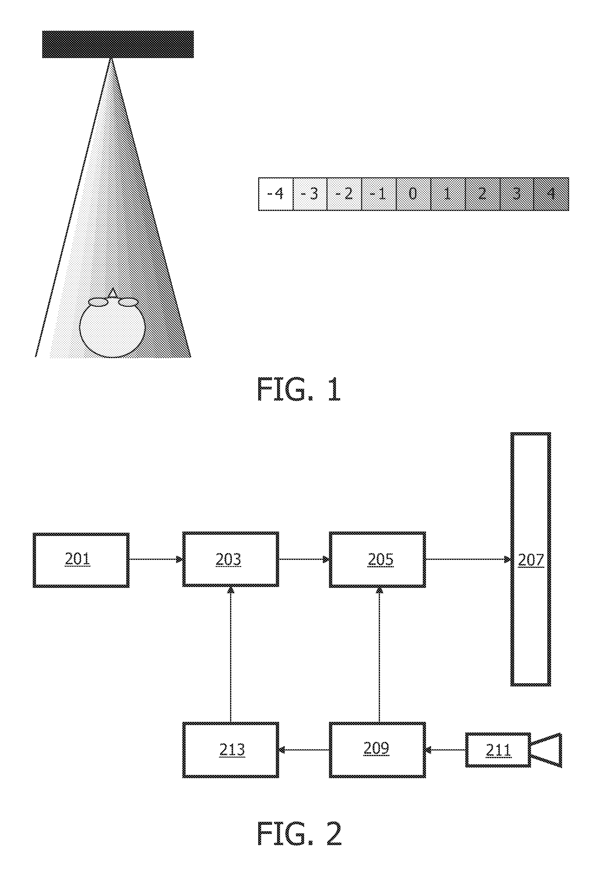
[0058]FIG. 2 illustrates an example of a three dimensional display system in accordance with some embodiments of the invention. The three dimensional display system is arranged to generate a plurality of views which correspond to different viewing angles of the same scene such that a user seeing different views in the two eyes may perceive a three dimensional image.

[0059]In the example, the three dimensional display system comprises an image data source 201 which provides image data and associated data that may allow generation of images for a three dimensional perception. In the specific example, the provided data is provided by a plurality of image layers corresponding to a background layer and one or more foreground layers for the background image. In addition, the provided data comprises a depth map for each image layer which contains a depth value for each pixel of the image layer.

[0060]For clarity and brevity, the following description will focus on the processing of a single ...


PUM


Abstract

A three dimensional display system comprises a display (207) presenting a plurality of views of a scene where each view corresponds to a viewing direction for the scene. A rendering unit (203) generates an image for each of the views. The rendering unit (203) is capable of generating differentiated images for neighbouring views containing differentiated image data providing a three dimensional depth effect when neighbouring views are viewed by different eyes of a viewer. A user processor (209) generates a user presence estimate in response to an attempted detection of a user in a viewing area for the display system. A 3D mode controller (213) modifies the three dimensional effect in response to the user presence estimate. For example, the display system may provide a two dimensional image when no user is present and a three dimensional image when a user is present. This may reduce discomfort experienced by viewers in suboptimal positions.

Description

FIELD OF THE INVENTION[0001]The invention relates to a three dimensional display system and a method of operating therefor.BACKGROUND OF THE INVENTION[0002]Three dimensional displays are receiving increasing interest and significant research is undertaken in how to provide three dimensional viewing perceptions without requiring the user to wear specific glasses or other inconvenient equipment, or requiring the users eyes to remain in a specific location.[0003]Three dimensional (3D) displays add a third dimension to the viewing experience by providing a viewer's two eyes with different views of the scene that is being watched. This can be achieved by having the user wear glasses to separate two views that are displayed. However, as this may be considered inconvenient to the user, it is in many scenarios preferred to use auto-stereoscopic displays that use means at the display (such as lenticular lenses, or barriers) to separate views, and send them in different directions where they ...

Claims


Application Information

Patent Timeline
Patent Type & Authority Applications(United States)
IPC IPC(8): G06T15/00G02B30/30
CPCG02B27/225H04N13/0404H04N13/0409H04N13/0475H04N13/0454H04N13/047H04N13/0447H04N13/305H04N13/31H04N13/351H04N13/359H04N13/368H04N13/373G02B30/30H04N13/111G06T17/00G06T19/00G06T15/00G06T17/20G06T15/10
Inventor GREMSE, FELIXPHILOMIN, VASANTHTOBIAS, MAARTEN
Owner LEIA INC
Learn More