
Method for Transferring a Base Station of a Wireless Communication Network from a Standby Mode to a Fully Activated Mode

Inactive Publication Date: 2011-08-11
CENTONZA ANGELO +3
View PDF8 Cites 107 Cited by
  • Summary
  • Abstract
  • Description
  • Claims
  • Application Information

AI Technical Summary

Benefits of technology

[0013]With the described method, operational costs for base stations may be saved and electromagnetic radiation from the base stations may be reduced or even eliminated during service inactivity while still providing coverage and service on demand.
[0083]For the described method, the synchronization of the user equipment may reduce the computation complexity for detection of an activation signal but is not necessarily needed.

Problems solved by technology

As long as a user equipment is connected in an active mode to a base station, it is not appropriate to switch that base station off.
A base station, which may be a NodeB (NB) or enhanced NodeB (eNodeB, eNB), especially a Home NB or Home eNB (H(e)NB), generates significant cost by its power consumption if there is no efficient standby mode solution applied in case of service inactivity.
Current state of the art base stations, including H(e)NBs, are little adaptive to their traffic and service needs.
Even if there is no user equipment connected the base station consumes similar amount of energy as in full load.
In off-load operational periods, for example during night time, the base station power consumption remains high probably without any request for service from a user equipment.
This procedure keeps operational cost high, and the economical balance bad since in principle the base station could have been entirely switched off.
However, the problem is how to wake-up the base station if totally switched off in case of a service request from a user equipment.
In a typical hierarchical deployment scenario low transmission power base stations may have access restrictions.
Such an operational mode keeps operational cost high and a reactivation complex.

Method used


Image

  • Method for Transferring a Base Station of a Wireless Communication Network from a Standby Mode to a Fully Activated Mode
  • Method for Transferring a Base Station of a Wireless Communication Network from a Standby Mode to a Fully Activated Mode
  • Method for Transferring a Base Station of a Wireless Communication Network from a Standby Mode to a Fully Activated Mode

Examples


Embodiment Construction

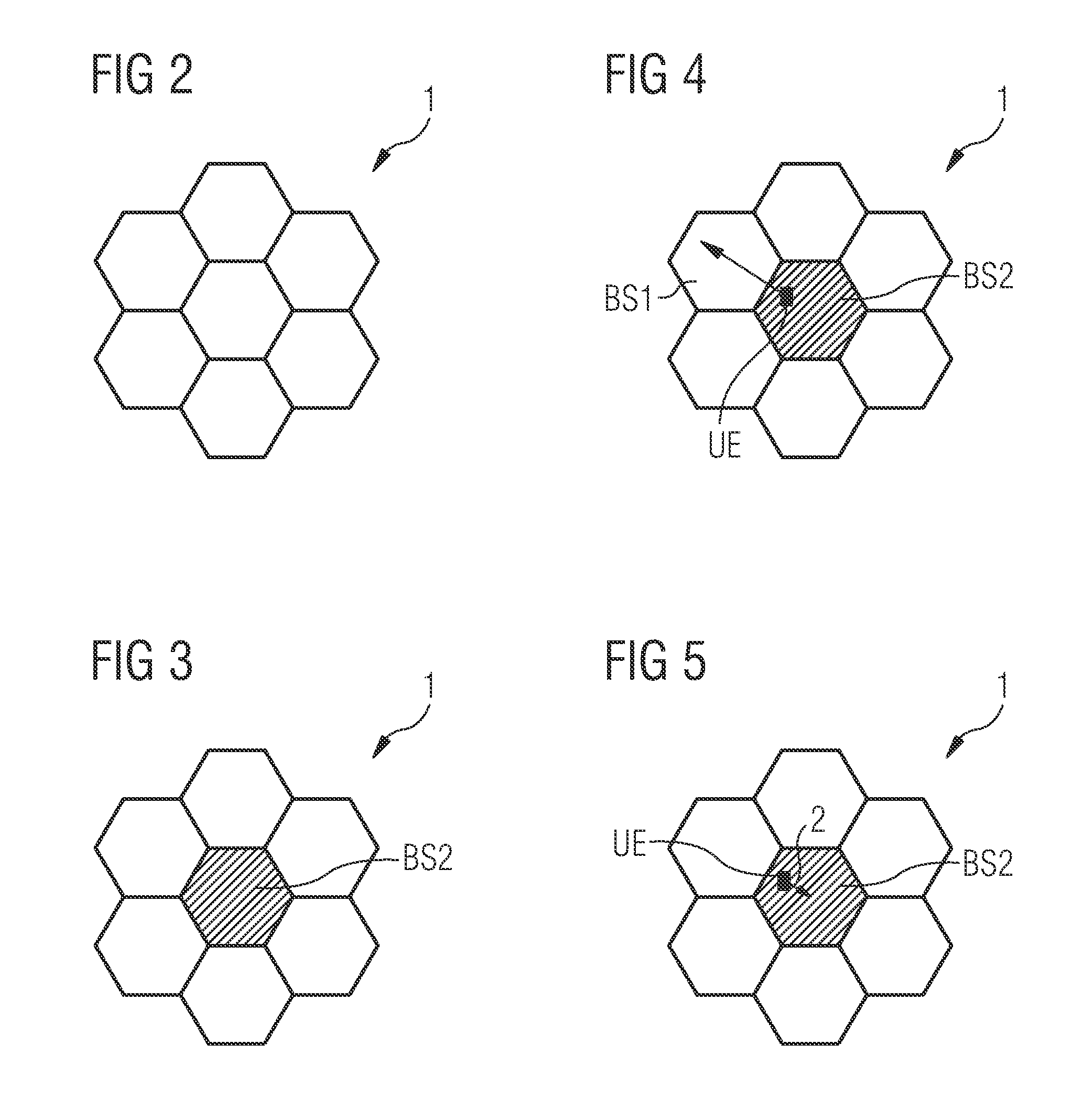
[0097]The illustration in the drawing is schematically. It is noted that in different figures, similar or identical elements are provided with the same reference signs.

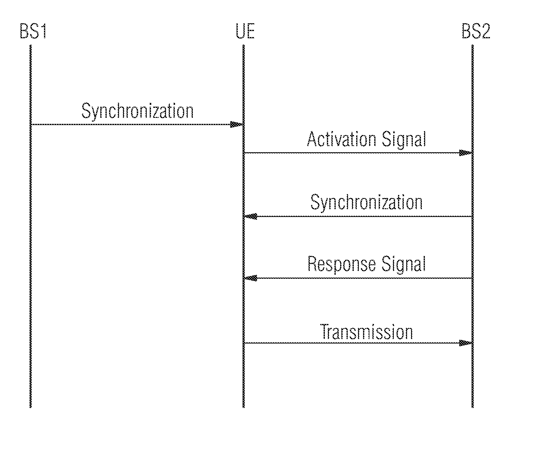
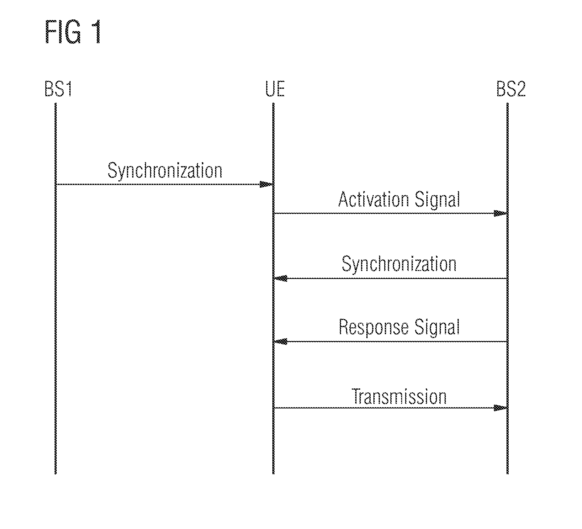
[0098]FIG. 1 shows a transactional flow diagram. In a first step, not shown, a user equipment UE, which is assigned to a home zone or base station, detects with any kind of location detection, for example WA fingerprint or GPS data, if its current location is in its home zone or in the range of the assigned base station.

[0099]In a second step, the UE synchronizes to the strongest received base station BS1. This step is optional. With the synchronization, the UE may get further information about the assigned base station, as for example periods of activity.

[0100]In a third step, the UE transmits an activation signal, i.e. a RACH burst, to the assigned base station BS2 with a wake-up preamble assigned to the base station BS2.

[0101]Subsequently, the UE waits for activation of BS2 transmitter and specifically for the tran...


PUM


Abstract

It is described a method for transferring a base station of a wireless communication network from a standby mode to a fully activated mode. The method includes sending an activation signal from a user equipment (UE) to the base station. The method further includes receiving the activation signal by the base station and transferring the base station (BS2) to the fully activated mode in response to the reception of the activation signal.

Description

FIELD OF INVENTION[0001]The present invention relates to the field of wireless communication networks. In particular, the invention relates to a method for transferring a base station from a standby mode to a fully activated mode. Further, the invention relates to a user equipment (UE), a base station, a computer-readable medium and a program element, which are adapted for performing the above mentioned method.ART BACKGROUND[0002]A typical mobile communication network comprises one or more base stations and one or more user equipments. In particular, such a mobile communication network may be a UMTS, a 3GPP Long-Term-Evolution (LTE) or 3GPP Long-Term-Evolution-Advanced network (LTE-A). In such networks, the user equipments are connected to a base station and may be handed over to another base station, if it is out of the range of the first base station or if the received signal quality to the other base station is higher than to the first base station. As long as a user equipment is...

Claims


Application Information

Patent Timeline
IPC IPC(8): H04W4/00
CPCH04J11/0069H04W52/0206H04W88/08H04W52/0235Y02D30/70
Inventor CENTONZA, ANGELOFORSSELL, MIKAMICHEL, JUERGENVESTERINEN, SEPPO IIMARI
Owner CENTONZA ANGELO
Learn More