
Multi-site MIMO cooperation in cellular networks

a cell network and multi-site technology, applied in the field of cellular communication systems, can solve the problems of not exploiting the channel state, affecting the signal quality of the network, so as to achieve the effect of more useful for medium and high speed users, and less useful for low speed users

Active Publication Date: 2011-08-11
MALIKIE INNOVATIONS LTD
View PDF28 Cites 30 Cited by
  • Summary
  • Abstract
  • Description
  • Claims
  • Application Information

AI Technical Summary

Benefits of technology

The invention provides methods for improving data transmission in cellular networks by designating multiple transmitting sites and assigning tones to each site for transmission. The methods also involve interlacing tones of cooperating sites and adjusting the beamforming to result in constructive addition of beams at the target mobile terminal. The technical effects include improved data transmission speed and reliability, as well as reduced interference and improved signal quality.

Problems solved by technology

Signals from these various sources may interfere, for example, by constructive superposition of signals from the various sites, with the signal expected or desired to be received by the mobile terminal.
A drawback of this known open loop cooperation technique was that it did not exploit channel state information (CSI) feedback to the cooperating site.
Consequently, this technique was more useful for medium and high speed users and less useful for low speed users where channel state information could be exploited to provide better quality of service.
Drawbacks of this technique included that it could only be applied to high geometry users, required pairing up of two or more users serviced by the same base station and required knowledge by the transmitting site (e.g. base station) channel conditions.
Since channel condition data or information from which channel conditions could be calculated by the transmitting site had to be transmitted from the mobile terminals, this technique resulted in higher feedback overhead.

Method used


Image

  • Multi-site MIMO cooperation in cellular networks
  • Multi-site MIMO cooperation in cellular networks
  • Multi-site MIMO cooperation in cellular networks

Examples


Embodiment Construction

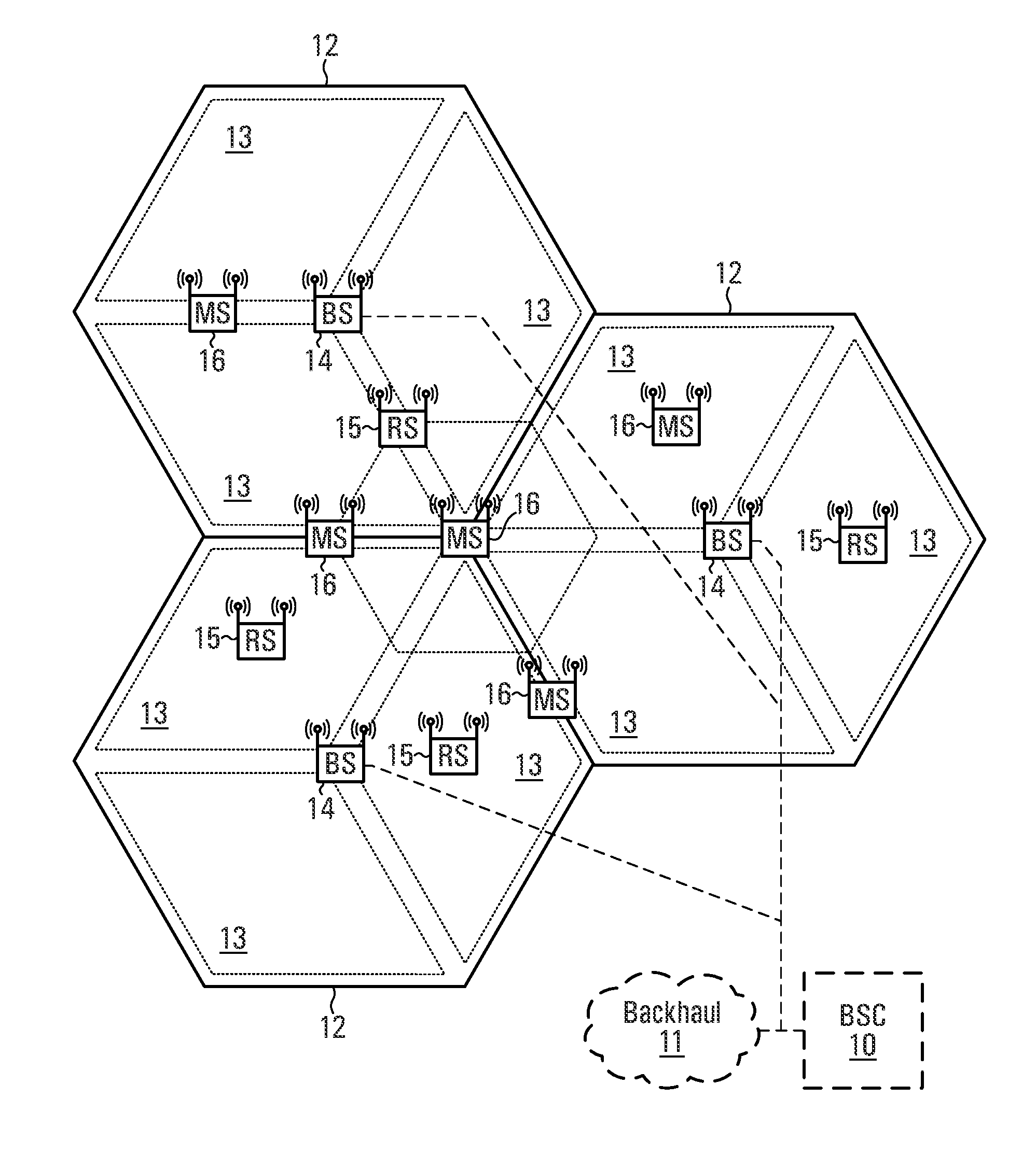
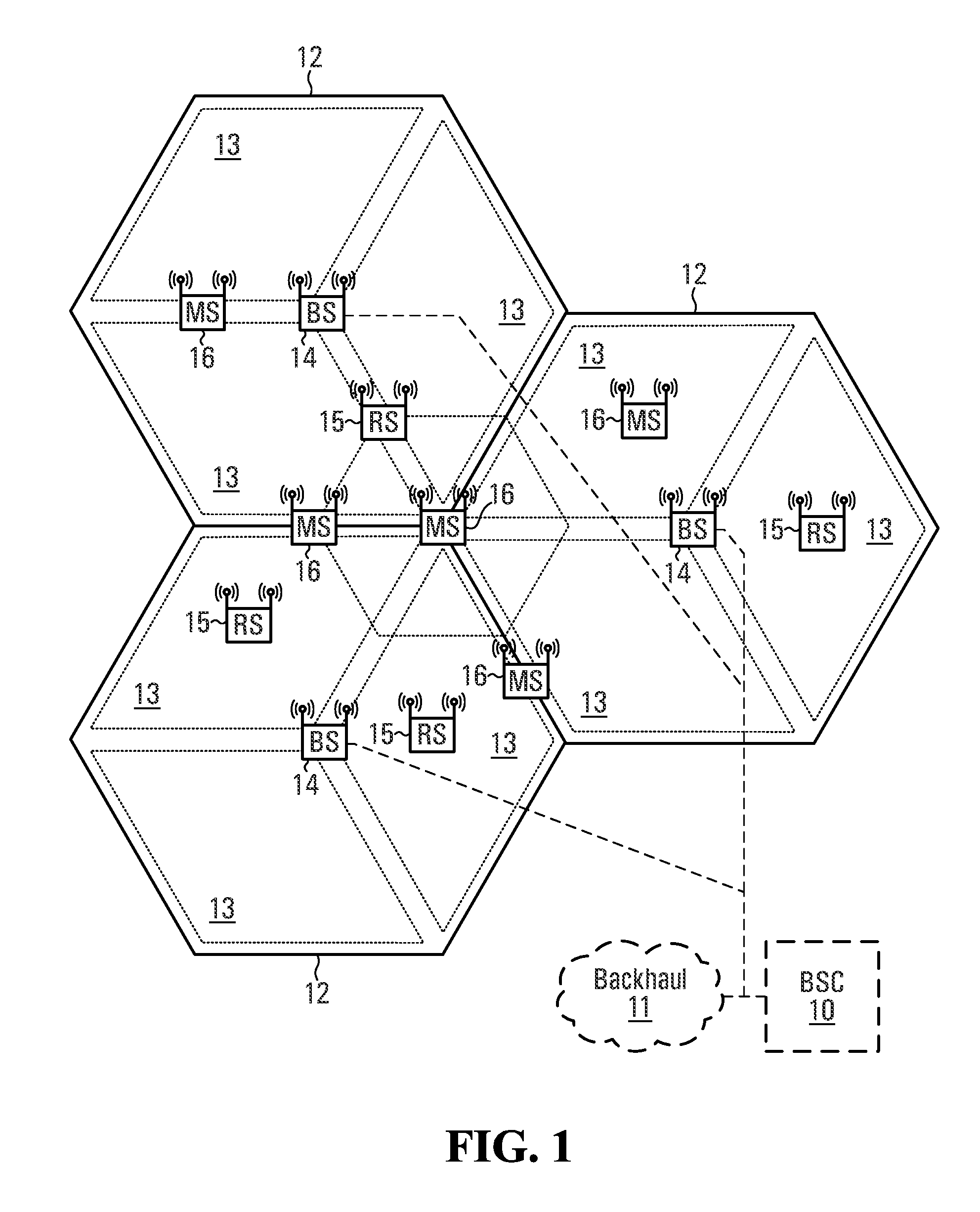
[0025]Referring to the drawings, FIG. 1 shows a base station controller (BSC) 10 which controls wireless communications within multiple cells 12, which cells are served by corresponding base stations (BS) 14.

[0026]In some configurations, each cell is further divided into multiple sectors 13 or zones (not shown). In general, each base station 14 facilitates communications using OFDM with mobile and / or wireless terminals 16, which are within the cell 12 associated with the corresponding base station 14. The movement of the mobile terminals 16 in relation to the base stations 14 results in significant fluctuation in channel conditions. As illustrated, the base stations 14 and mobile terminals 16 may include multiple antennas to provide spatial diversity for communications. In some configurations, relay stations 15 may assist in communications between base stations 14 and wireless terminals 16. Wireless terminals 16 can be handed can be handed off 18 from any cell 12, sector 13, zone (n...


PUM


Abstract

A method of serving a given data stream to a target mobile terminal, in a cellular communications network that includes a plurality of transmitting sites wherein each transmitting site including at least one antenna, is provided. The method includes designating at least two of the plurality of transmitting sites as cooperating sites; assigning tones to each transmitting site from a sub-band associated with the cooperating sites; dividing the data stream into at least two sub-data streams, each of the sub-data streams for transmission over selected tones; and interlacing tones of the cooperating sites in accordance with a selected one of a time switching and a frequency switching transmit diversity technique. Other techniques for multi-site MIMO cooperation are also provided.

Description

CROSS-REFERENCE TO RELATED APPLICATIONS[0001]This application claims the benefit of U.S. Provisional Patent Application No. 61 / 244,115, filed in the United States Patent Office on Sep. 21, 2009, the contents of which are incorporated by reference herein.[0002]This application is a continuation-in-part of the non-provisional application (serial number tbd) resulting from conversion under 37 C.F.R. §1.53(c)(3) of U.S. provisional patent application No. 61 / 244,115 filed on Sep. 21, 2009, which claims the benefit of U.S. provisional patent application No. 61 / 098,978 filed on Sep. 22, 2008.FIELD OF THE INVENTION[0003]This application relates to cellular communications systems. More specifically, this application relates to MIMO transmission techniques between cellular sites.BACKGROUND OF THE INVENTION[0004]Cellular networks are divided into many small geographic areas, called cells or sites. Each cell is adjacent to one or more cells. Collectively, the cells provide cellular service to a...

Claims


Application Information

Patent Timeline
Patent Type & Authority Applications(United States)
IPC IPC(8): H04B7/212
CPCH04W72/1231H04L1/0071H04L1/0625H04B7/0671H04B7/12H04L1/0656H04L1/0026H04L5/0035H04B7/0669H04L1/0668H04B7/0689H04L5/0007H04L5/001H04L5/003H04B7/024H04W72/542
Inventor BALIGH, MOHAMMADHADIMA, JIANGLEIXU, HUA
Owner MALIKIE INNOVATIONS LTD
Learn More