Method for making a nano-optical antenna array

a technology of nano-optical antennas and antenna arrays, applied in vacuum evaporation coatings, sputtering coatings, coatings, etc., can solve the problems high cost of nano-optical antenna arrays

Inactive Publication Date: 2011-08-11
TSINGHUA UNIV +1
View PDF15 Cites 20 Cited by
  • Summary
  • Abstract
  • Description
  • Claims
  • Application Information

AI Technical Summary

Benefits of technology

[0006]What is needed, therefore, is to provide a low-cost and simple method for making a nano-optical antenna array.

Problems solved by technology

However, the cost of the nano-optical antenna array is high because the lithography system, the photoresist, and the process of making the nano-optical antenna array are complicated.

Method used


Image

  • Method for making a nano-optical antenna array
  • Method for making a nano-optical antenna array
  • Method for making a nano-optical antenna array

Examples


Embodiment Construction

[0013]The disclosure is illustrated by way of example and not by way of limitation in the figures of the accompanying drawings in which like references indicate similar elements. It should be noted that references to “an” or “one” embodiment in this disclosure are not necessarily to the same embodiment, and such references mean at least one.

[0014]References will now be made to the drawings to describe, in detail, various embodiments of the present method for making a nano-optical antenna array.

[0015]A method for making a nano-optical antenna array of one embodiment includes the following steps of:

[0016]step (a): providing an insulative substrate;

[0017]step (b): hydrophilicly treating the insulative substrate;

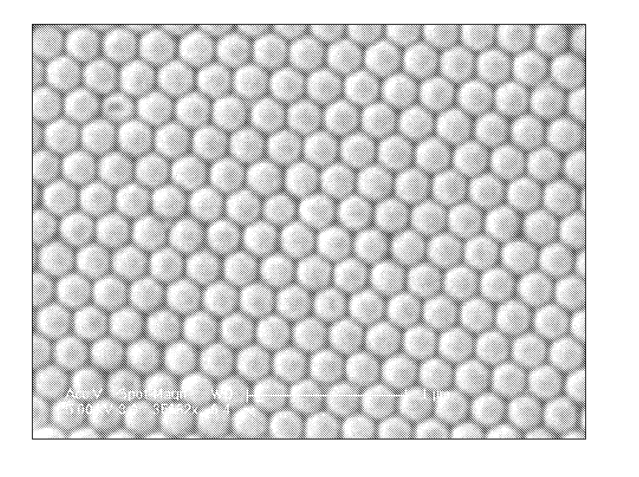
[0018]step (c): forming a monolayer nanosphere array on the insulative substrate;

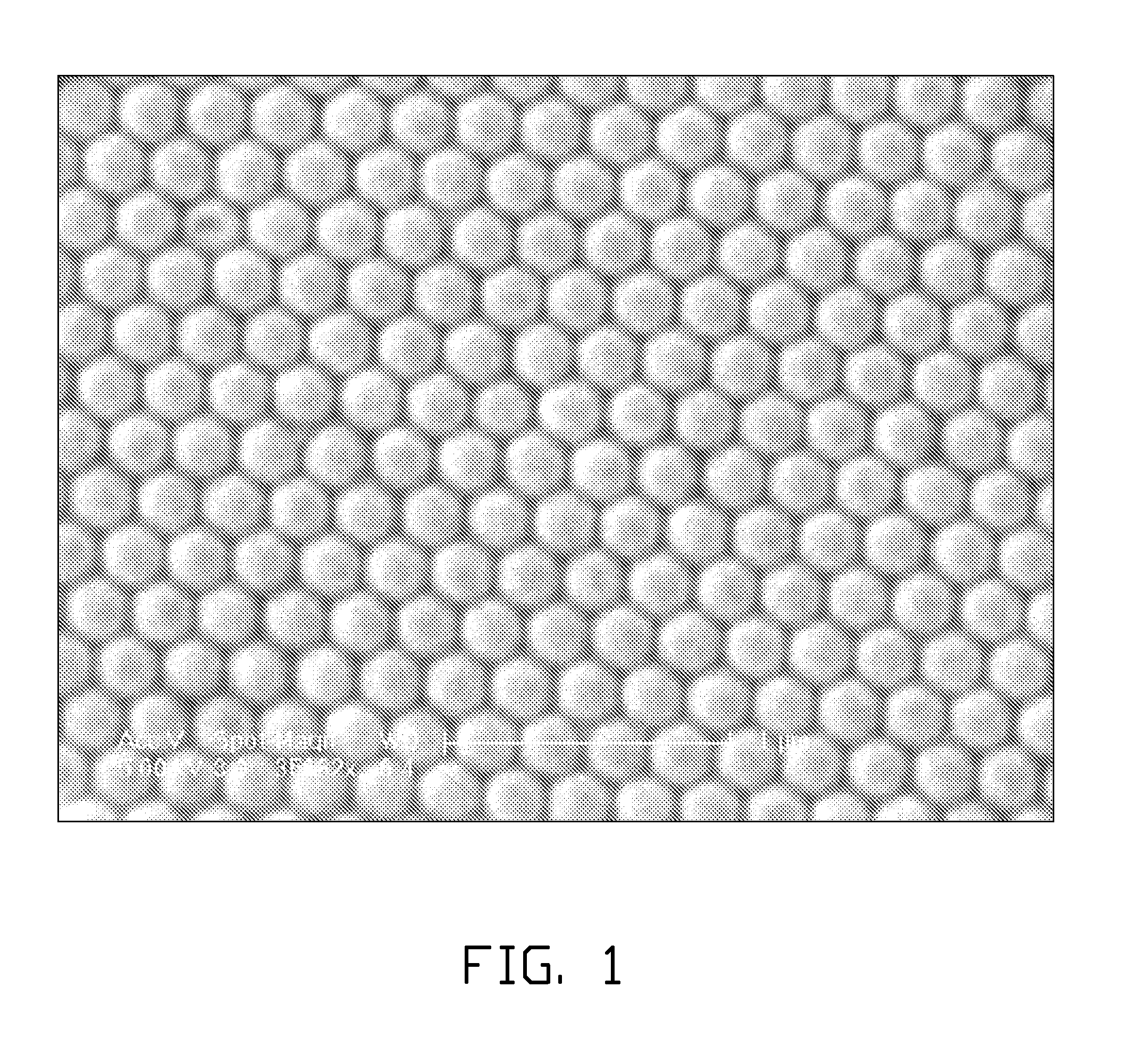
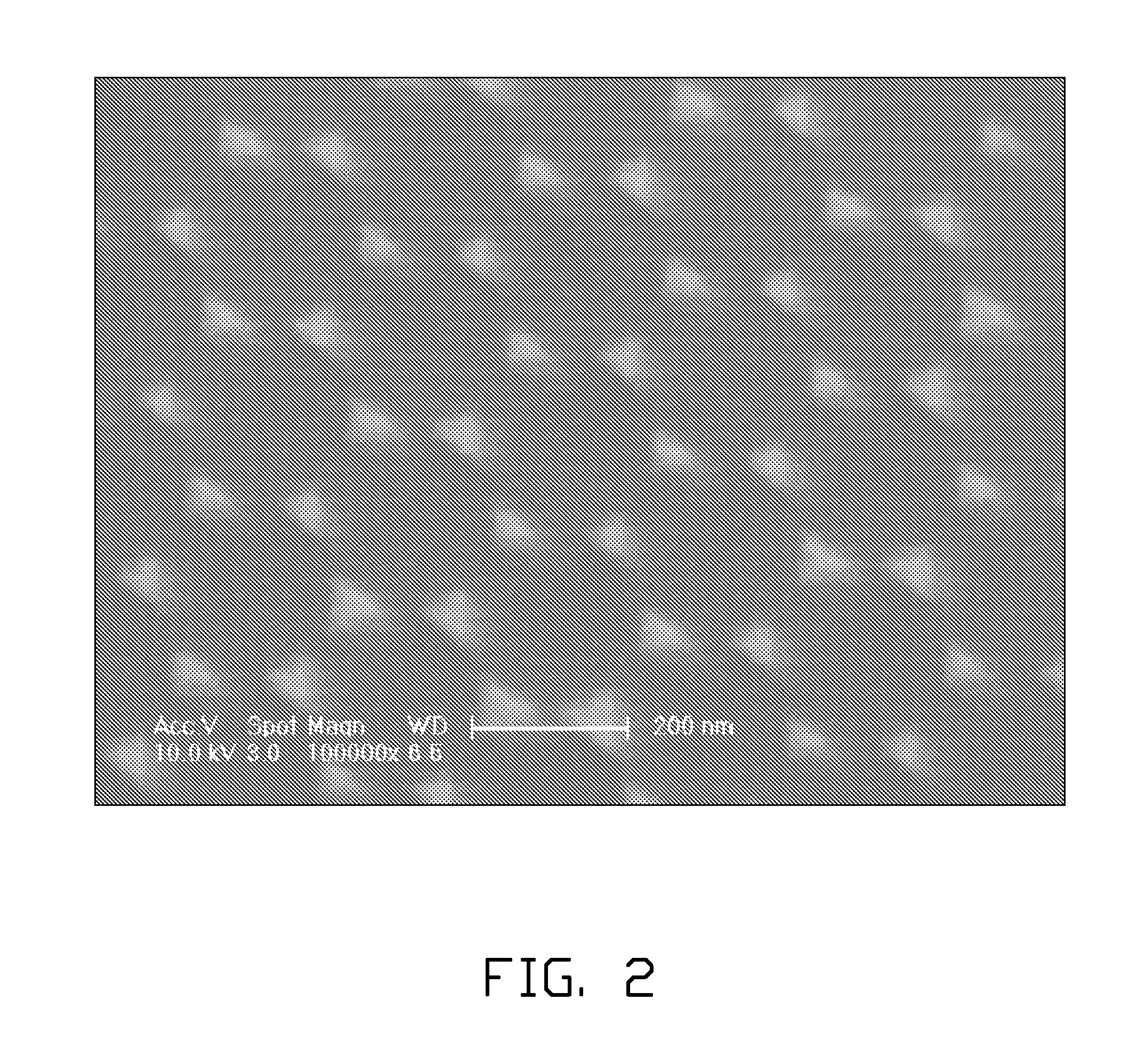
[0019]step (d): depositing a film on the monolayer nanosphere array;

[0020]step (e): removing the monolayer nanosphere array.

[0021]In step (a), the insulative substrate can be made of a rigid or flex...


PUM

PropertyMeasurementUnit
angleaaaaaaaaaa
speedaaaaaaaaaa
thicknessaaaaaaaaaa

Abstract

A method for making a nano-optical antenna array includes following steps. First, an insulative substrate is provided. Second, the insulative substrate is hydrophilicly treated. Third, a monolayer nanosphere array is formed on the insulative substrate. Fourth, a film is deposited on the monolayer nanosphere array. Fifth, the monolayer nanosphere array is removed.

Description

CROSS-REFERENCE TO RELATED APPLICATIONS[0001]This application claims all benefits accruing under 35 U.S.C. §119 from China Patent Application No. 201010110157.1, filed on Feb. 6, 2010 in the China Intellectual Property Office, disclosure of which is incorporated herein by reference.BACKGROUND[0002]1. Technical Field[0003]The present disclosure relates to a method for making a nano-optical antenna array.[0004]2. Description of Related Art[0005]Nano-optical antenna arrays are widely used and studied. A method for making the nano-optical antenna array usually includes the step of lithography. However, the cost of the nano-optical antenna array is high because the lithography system, the photoresist, and the process of making the nano-optical antenna array are complicated.[0006]What is needed, therefore, is to provide a low-cost and simple method for making a nano-optical antenna array.BRIEF DESCRIPTION OF THE DRAWINGS[0007]Many aspects of the embodiments can be better understood with r...

Claims


Application Information

Patent Timeline
Patent Type & Authority Applications(United States)
IPC IPC(8): B05D3/06B05D3/10C23C14/34
CPCH01Q21/061H01Q21/0087
Inventor ZHU, ZHEN-DONGLI, QUN-QINGCHEN, MOZHANG, LI-HUIFAN, SHOU-SHAN
Owner TSINGHUA UNIV
Why Eureka
Try Eureka