Linear X-ray detector using fiber optic face plate to alter optical path

a fiber optic face plate and detector technology, applied in the direction of material analysis using wave/particle radiation, instruments, radiation control devices, etc., can solve the problem that x-rays cannot be focused, and achieve the effect of high resolution, low cost and production

Active Publication Date: 2011-04-28
X SCAN IMAGING CORP
View PDF16 Cites 2 Cited by
  • Summary
  • Abstract
  • Description
  • Claims
  • Application Information

AI Technical Summary

Benefits of technology

[0038]Still another advantage of the present invention is that the existing low-cost and volume production of the linear FOFP's allows the X-ray Detector Systems; according to the present invention; to also be produced at low cost.
[0039]Another advantage obtained by using a FOFP in the system is the ability to transfer the images from the scintillating layer to the image sensor array, hence providing a means to alter and modify the optical path while preserving high resolution, i.e., the MTF, modulation transfer function.
[0040]Still another advantage is that the present invention provides low-cost and simple methods of shielding the radiation sensitive components of the system from exposure to damaging X-ray flux.
[0041]Another advantage of the present invention is that it enables the manufacture of a small, portable X-ray Detector Machine.
[0042]Yet another advantage of the present invention is that with the small enclosure size required and the methods of radiation shielding, it is possible to design Dual or Multi X-ray Scanning Machines enclosed in the same space currently used to enclose a Single X-ray Scanning Machine. The Dual or Multi X-ray Scanning Machines can be used for scanning a target simultaneously in different X-ray energy ranges for better detection.
[0043]Still another advantage arising from the small size and shielding properties of the present invention is that it is possible to implement a three-dimensional X-ray scanner, in which two scanning detector systems are positioned orthogonally with respect to each other.

Problems solved by technology

It is well known that X-rays cannot be focused, and can only be controlled with a shield (typically formed from lead or other heavy metal) with aperture stops.

Method used


Image

  • Linear X-ray detector using fiber optic face plate to alter optical path
  • Linear X-ray detector using fiber optic face plate to alter optical path
  • Linear X-ray detector using fiber optic face plate to alter optical path

Examples


Embodiment Construction

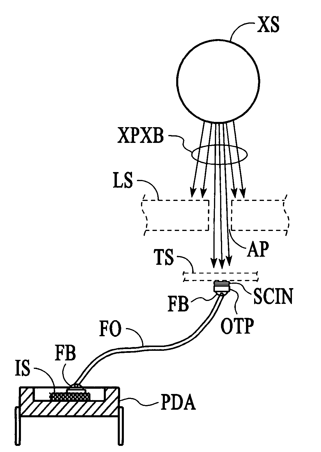
[0055]The present invention is a linear X-ray detector system 1. The detector system 1 is based on a unique image transferring characteristics of a fiber optic face plate 13, as illustrated in FIG. 6. The fiber optic face plate 13 is installed in the system 1 as illustrated in FIG. 7. FIG. 7 is a cross-sectional view of the X-ray detector system. The length of the detector perpendicular to the plane of the paper is determined by the length of the specimen to be scanned. The detector system 1 comprises a layer of scintillating material 14, a fiber optic face plate (FOFP) 13, and an array of image sensors 16. Some of the viable options for the scintillating material layer 14 are Gd2O2S:Tb (GOS or GADOX), CsI(Tl), and CdWO4. As described more fully below, the layer of scintillating material 14 is placed on the top surface of the FOFP 13 and is used to convert the impinging X-ray energies into visible light which can be detected efficiently by the image sensor array 16. FIG. 6 illustrat...


PUM

PropertyMeasurementUnit
angleaaaaaaaaaa
ninety degrees angleaaaaaaaaaa
thicknessaaaaaaaaaa

Abstract

A radiation damage resistant linear X-ray detector system based on a unique image transferring principle to alter the optical path and thus reduces or eliminates the X-ray radiation damage on the electrical components of the detector system. The system includes a layer of scintillating material, a fiber optic face plate (FOFP), and an array of image sensors. One face of the FOFP is bonded to the surface of the image sensors. The layer of scintillating material, such as Gd2O2S:Tb (GOS or GADOX), CsI(TI), or CdWO4, is placed on other face of the FOFP and used to convert the impinging X-ray energies into visible light which can be detected efficiently by the image sensor array. The FOFP is used to transfer the visible light from the scintillating layer onto the image sensor array after the X-ray flux has been converted. The photon energy of the visible light is collected with a scanning image sensor array that converts the photon energy proportionally into electrical video signals and enables the signals to be processed using standard image processing software and equipment.

Description

CROSS-REFERENCE TO RELATED APPLICATIONS[0001]The present invention is related to U.S. Pat. Nos. 7,463,717 B2 and 7,463,716 B2, in which an optical component is used to alter the optical path away from the X-ray beam path to avoid radiation damage on the electrical components in an X-ray detecting system.BACKGROUND OF THE INVENTION[0002]1. Field of the Invention[0003]The present invention pertains generally to the field of solid-state X-ray imagers and displays, and more particularly is an improved method that structurally alters the optical path to reduce or avoid radiation damage to the semiconductor components used to process the detected X-ray images.[0004]2. Background of the Invention[0005]As used in this disclosure, X-rays are defined as ionizing electromagnetic radiation that is damaging to semiconductor-based image sensor array. X-rays also include the radiation known as “extreme ultraviolet radiation” and “gamma rays”. Since few X-rays with energies exceeding 10 KeV are cap...

Claims


Application Information

Patent Timeline
Patent Type & Authority Applications(United States)
IPC IPC(8): G01T1/20G01N23/04
CPCG01T1/20
Inventor TSENG, HSIN-FUYANG, LINBO
Owner X SCAN IMAGING CORP
Why Eureka
Try Eureka